
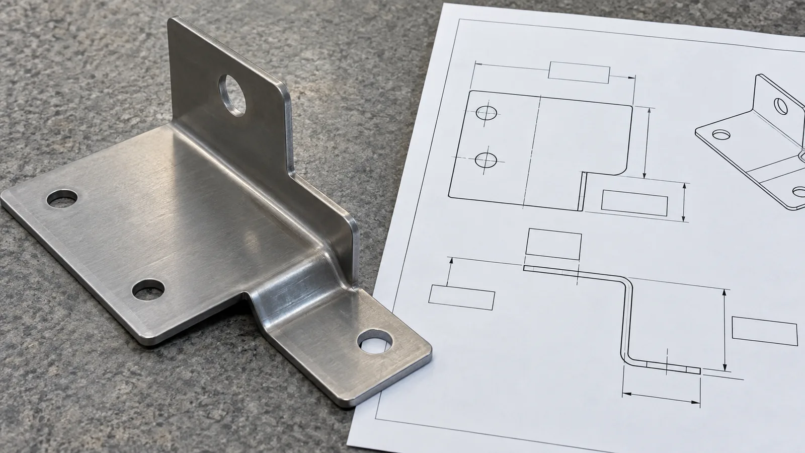
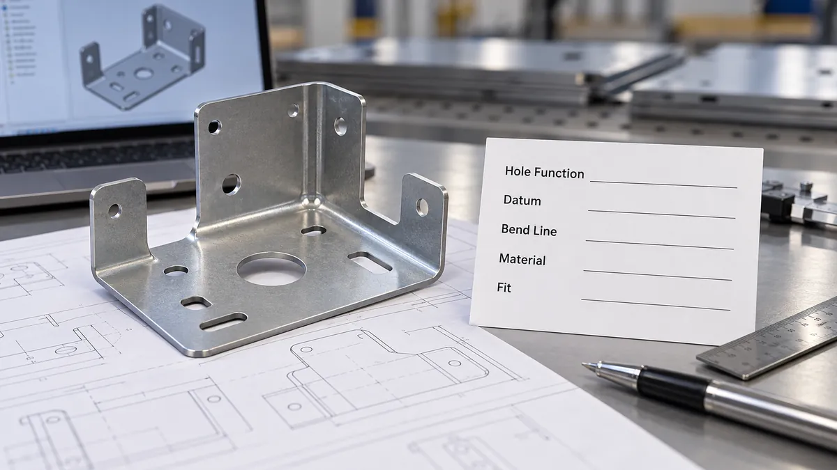
When a mounting hole sits close to a sheet-metal bend, the buyer should control the hole’s function and datum, the bend line and radius, material and thickness, downstream fit, and how the finished sample will be measured. Sheet metal hole distance from bend line distortion mounting plate concerns cannot be solved with a universal spacing number; the acceptable relationship depends on the geometry, forming route, and product interface. Buyers searching the exact phrase “sheet metal hole distance from bend line distortion mounting plate” should treat it as a system-level question answered with the actual drawing and sample, not as a universal rule.
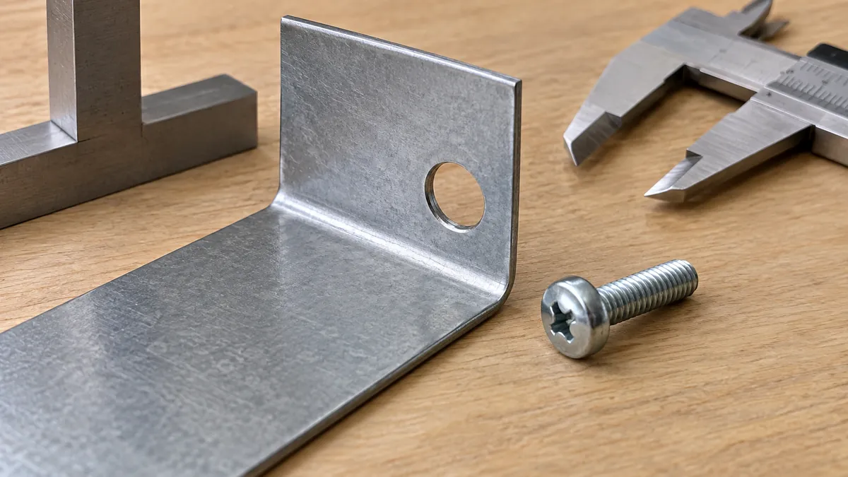
For related category context, see the custom bathroom hardware manufacturer and this related buyer guide.
Why can a nearby hole affect the finished mounting plate?
Forming changes the shape of the sheet around a bend. A hole or slot close to that zone may move, distort, become harder to inspect, or affect the remaining material around the feature. The outcome depends on the hole’s size and shape, the bend geometry, material, thickness, edge condition, and process. A flat-pattern dimension alone may not communicate where the finished hole must land.
The important question is often functional rather than visual. Does the hole locate a screw, allow adjustment, engage a mating component, or provide clearance? A slightly changed hole may be acceptable for one function and unacceptable for another. The buyer should identify why the feature exists and what surface or assembly datum controls its final position.
A mounting plate may be bent before or after other operations depending on the design and process. Different sequences can change access, alignment, burr orientation, and the way dimensions are inspected. The buyer should not prescribe a sequence without understanding its implications, but can ask the supplier to state the proposal and highlight features needing sample confirmation.
Adjacent holes also interact with finish and assembly. Coating or another finish can affect the final opening, while a screw head, washer, or mating bracket may require a flat landing area. Review the hole in the completed part and assembly, not only on the blank. Avoid assuming the hole’s center remains functionally correct because a flat drawing shows a precise coordinate.
What should the drawing say about hole function and datums?
Label each nearby hole or slot by function: fastening, location, adjustment, clearance, or another intended role. Identify the mating component and the direction from which a fastener enters. If a slot provides adjustment, clarify its useful travel and orientation. The supplier can then understand whether the critical requirement is center position, edge distance, slot direction, fit, or assembly access.
Establish datums on the finished part. A flat blank coordinate may be useful for programming, but the assembled product references formed faces and mounting surfaces. Define which face or edge anchors the inspection and how the hole’s position relates to the bend. If the bend is the locating feature, say so; if a separate edge or surface is primary, avoid making the bend line an ambiguous reference.
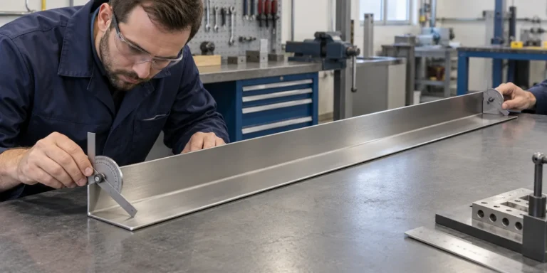
Show the bend line, angle, inside or outside radius reference, material, thickness, and direction of forming on a clear section view. Include the hole diameter or slot dimensions and the required positional relationship. If the drawing intentionally leaves a process-dependent dimension for the supplier to propose, mark it as open for review and require approval before the sample is released.
Avoid copying a generic minimum-distance rule from another part. The relationship between a hole and a bend is sensitive to size, material, tooling, and what happens after forming. An accepted sample may help establish a project-specific requirement, but it must be tied to the same design, material, and process assumptions that produced it.
| Feature or decision | What to identify | Sample question |
|---|---|---|
| Hole function | Fastening, locating, adjustment or clearance | What does correct fit mean for this feature? |
| Datum scheme | Finished face, bend, edge or mating surface | From what stable reference is position measured? |
| Bend definition | Line, direction, angle and radius reference | Which finished geometry controls the nearby hole? |
| Material/process | Grade/form, thickness, cut edge and sequence | Does the sample represent the approved combination? |
| Assembly interface | Fastener, washer, mating part and access | Can the part be assembled without forcing or damage? |
| Acceptance record | Revision, method, result and disposition | Can another reviewer repeat the decision? |
How do hole-to-bend issues differ from radius cracking or angle variation?
Hole-to-bend clearance focuses on the location and shape of a feature near a bend and whether it remains usable after forming. Bend-radius cracking focuses on material strain and surface integrity around the bend itself. Angle variation focuses on the resulting angle or flange position. The problems can coexist, but a buyer question about one should not be mistaken for a complete answer to the others.
A hole can remain round and still be in the wrong place relative to a finished flange. Conversely, its center may be acceptable while the edge becomes distorted or too close to the bend for a washer or screw head. Therefore, inspection should include the hole’s function, clearance, and assembly behavior rather than measuring only overall dimensions.
If the feature is near a cosmetic surface, the visible result may also matter. A local mark, rough edge, or change in reflection can become more obvious after finishing. State which surfaces are visible and whether appearance is a separate acceptance item. A sample approval should not imply that all surface or corrosion risks have been addressed by checking hole position.
The project record should keep these criteria distinct. Identify which measurement covers hole position, which covers bend geometry, which checks cracks or surface damage, and which verifies assembly fit. Distinct inspection points make corrective discussion more useful and prevent a single broad statement such as bend area accepted from masking an unresolved functional issue. In this context, “sheet metal hole distance from bend line distortion mounting plate” is a shorthand for a documented design-and-sample decision, not a preset engineering value.
How should buyers compare design and manufacturing options?
One option is to move the hole away from the bend, if product function and envelope permit. Another is to change the bend geometry, plate profile, fastener, or mating bracket. A process engineer may recommend a different sequence or feature preparation. Each option can affect appearance, part count, strength, packaging, or assembly, so the buyer should review the complete product rather than optimize a local distance in isolation.
If a hole must remain close to the bend, request a representative sample and identify the exact finished measurement. A flat coupon without the same bend, hole size, material, and edge condition may be informative but cannot prove the final interface. The sample should also use the intended finishing route if the final opening or surface affects fit.
The comparison should include consequences for downstream assembly. Check the screw path, tool access, head seating, mating-part clearance, and whether the bent flange blocks insertion. If the mounting plate is installed against another component, use that component or a controlled fixture in the sample review. The best geometry is the one that meets the documented product need under its actual assembly conditions.
A supplier quotation should identify whether the proposed process and inspection are included. Ask whether any special fixture, secondary operation, or measurement plan is assumed. Do not presume a supplier has a particular measurement instrument or automated process unless confirmed. For small batches and custom development, direct discussion of drawing revisions and sample evidence can help resolve uncertainty before bulk release.
What is a repeatable sample inspection plan?
Start by identifying the sample, material, drawing revision, finish, and process route. Record the bend angle and radius definition, hole dimensions, datum references, and any edge preparation. If the supplier used a substitute material or temporary process, list that difference and decide whether it can represent the intended production condition.
Measure the hole after forming from the agreed finished-part datum. Capture the feature’s center or boundary as appropriate to its function. Check whether the hole remains circular or the slot retains its intended shape, whether the fastener or mating feature passes, and whether there is sufficient contact area for the intended screw head or washer. Choose tools and inspection method based on the drawing and risk.
Check the assembly under the expected orientation and installation sequence. Confirm that a fastener can be inserted, aligned, and tightened without forcing the part into position or damaging the finish. Look for interference with nearby walls, brackets, or components. If the hole provides adjustment, verify the usable range with the mating part rather than judging the slot in isolation.
Record acceptance in clear language. If the sample is accepted with a deviation, identify the exact deviation, revision, and scope. If it is rejected, state whether the cause is feature position, deformation, edge condition, assembly access, or another observed issue. Avoid turning one sample observation into a numerical production guarantee unless the responsible parties have defined and validated the requirement. The phrase “sheet metal hole distance from bend line distortion mounting plate” should therefore remain tied to the approved configuration and its inspection record.
Which changes should trigger a targeted recheck?
Moving the hole, changing its diameter or slot shape, changing the bend line or radius, or changing thickness can alter the local relationship. A material substitution may change forming behavior. Each change should be assessed for the characteristics it affects, rather than automatically treating every revision as identical or requiring every inspection step again.
A change in cut route or tooling can influence the blank edge and feature shape. A different bend sequence or setup can affect the final hole-to-datum relationship. If the process changes after sample approval, ask the supplier to identify the affected dimensions and provide the evidence needed to maintain fit. The sample record should name the route that it represents.
Finish changes can alter the hole’s usable opening, appearance, or fastener contact. Assembly hardware changes may also change how much positional variation the product can tolerate. Recheck the final configuration when a screw, washer, bracket, finish, or mating component is revised; approval of an uncoated metal sample does not automatically approve a coated assembled unit.
Use change control to link drawing, bill of materials, inspection record, assembly instructions, and packaging to one revision. For a repeat order, confirm the product still matches the approved sample and the buyer’s current requirements. This is especially valuable when the article’s topic is a small feature with a large downstream effect: the hole may be visually minor but govern alignment, assembly time, and field fit.
Buyer approval checklist
Use the sample approval form to capture both a measurement and a functional outcome. For example, name the hole, datum, inspection method, mating fastener, and assembly observation, then attach a photograph of the installed plate. This keeps the approval tied to the buyer’s real decision and makes any later drawing or process change easier to assess without relying on an ambiguous dimension note.
- Name the hole or slot function and the mating fastener/component it serves.
- Show finished-part datums, bend line/direction/radius, material and thickness on the controlled drawing.
- Identify nearby holes, slots, edges, cut condition, finish, and features that could affect assembly.
- Agree how the formed sample is measured and checked with the actual mating part or controlled fixture.
- Record deviations and define targeted rechecks for changes to hole geometry, material, bend, route, finish or hardware.
Frequently asked questions
Is there a standard distance every hole should keep from a bend?
No universal distance fits every hole, material, thickness, bend, and process. Use the drawing and a representative sample to establish the project’s functional requirement.
Should hole position be measured before or after bending?
The buyer should define the finished feature and datum that control assembly. A flat-blank check may support process control but does not replace finished-part verification when forming can affect fit.
Can a hole near a bend be accepted if the screw fits?
Screw fit is one check. Also consider location, edge condition, head seating, mating geometry, appearance, and any adjustment function specified for the product.
Is this the same as bend-radius cracking?
No. Cracking concerns material/surface integrity at the bend; hole-to-bend review concerns feature position, shape, clearance, and assembly after forming. Check both if both matter.
Does this article state Koitor’s production tolerance?
No. It gives a buyer framework. Any numerical tolerance, exact product capability, and process commitment must be agreed for the specific drawing and sample.
Plan a buyer-ready product specification
Share your drawing, product range and sample requirements so the project team can review the relevant manufacturing questions.
OEM / PRIVATE LABEL
Turn this sourcing guide into a product brief
Share your target product, size, finish, order quantity and packaging requirements. Your team receives a practical manufacturability review before quotation.
 English
  Español
  Português
  Français
  Deutsch
  العربية