
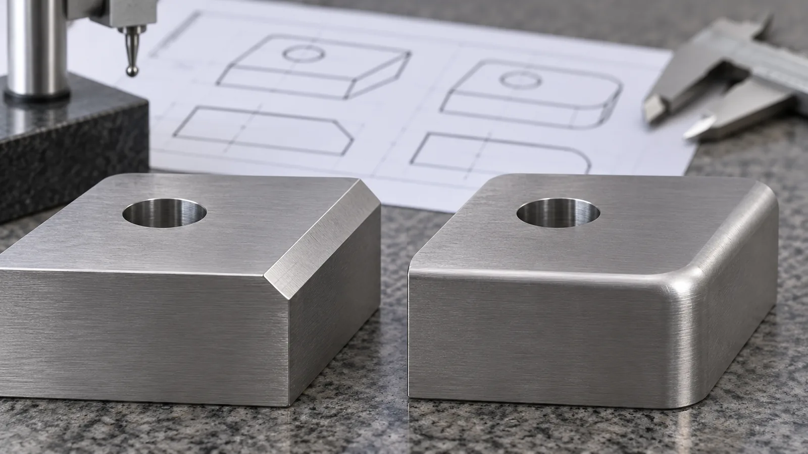
Chamfer vs fillet is the choice between two different edge profiles. A chamfer replaces an edge with a flat angled face, while a fillet creates a rounded transition between adjoining faces. A buyer should identify which edges are affected and specify the required angle and setbacks or radius, along with the intended fit, appearance or assembly purpose. The word “deburr” alone does not define either controlled geometry, and neither shape by itself proves strength, safety, cost or manufacturability for a particular metal hardware part.

In the chamfer vs fillet comparison, a chamfer is a flat, sloped transition cut or formed along an edge. A fillet is a curved transition between neighboring surfaces. These are geometric descriptions, not complete process instructions. The terms can refer to different internal or external edges and may appear in a CAD model, drawing, inspection note or quotation. Buyers should check that the same intended feature is being discussed in each document.
Shapr3D’s current Chamfer tool documentation distinguishes beveled flat transitions from rounded fillet transitions and describes equal-distance and two-distance chamfer settings. This helps explain geometry, but a CAD operation does not establish that a particular factory can make the feature or hold a particular tolerance. The design must still be reviewed against material, part form, process, access and finish.
A chamfer is not automatically a 45-degree feature, which is a key point in any chamfer vs fillet drawing review. Equal setbacks on two perpendicular faces can produce a 45-degree bevel in the CAD example, but other designs use unequal setbacks or a different angle. A fillet is not a universal radius; the drawing or controlled model should define the actual radius or an agreed edge condition. Never infer a dimension from a screenshot or a generic convention if the specification needs a precise result.
The word “fillet” also appears in welding terminology. A fillet weld is a weld type and joint description; it does not mean that every adjacent part edge has a rounded fillet geometry. Keep the context explicit: a weld callout describes a joint, while an edge callout describes the transition between surfaces unless the controlled drawing says otherwise.
Choose the feature based on the intended contact, fit, appearance or manufacturing requirement, then verify that the exact shape is defined. The name alone does not state why it is needed or what would count as acceptable.
A chamfer may be used where a flat bevel is part of an appearance detail, an assembly lead-in or a defined edge treatment. A fillet may be selected where the design requires a rounded transition or a particular appearance at the corner. Those are possible design intentions, not guarantees that one feature always assembles more easily or is always stronger. The related faces, mating parts and process determine whether the chosen feature serves the actual purpose.
Ask the designer to state the edge’s role. Is the edge visible after installation? Does another component pass over it? Does the feature create clearance for a screw head, insert, tube, gasket or cover? Is the concern a sharp-edge condition, or is a controlled profile required for fit? Is the feature intended to preserve a cosmetic surface? These questions turn an ambiguous preference into a reviewable requirement.
For a cosmetic edge, a rendered image may help communicate intent but should not replace the dimensioned drawing. For a mating interface, confirm the opposing component, its tolerance and assembly direction. For a handling-related requirement, use the applicable product specification and evaluation method; a visual assumption that an edge “looks rounded enough” is not a safety certification.
| Chamfer | Flat angled face at an edge | Edge location, angle or setbacks, affected length and tolerance if required | Assuming every chamfer is 45 degrees |
|---|---|---|---|
| Fillet | Curved transition between faces | Edge location, radius, tangent/continuity intent and applicable tolerance | Assuming a fillet automatically improves strength or safety |
| Deburr / edge break | General removal or reduction of burrs/sharpness as defined by the specification | Which edges, limits, acceptable variation and inspection method | Treating the note as a precise chamfer or radius callout |
| Fillet weld | Weld/joint terminology | Joint location, weld symbol/size and applicable acceptance criteria | Confusing a weld profile with a rounded part edge |
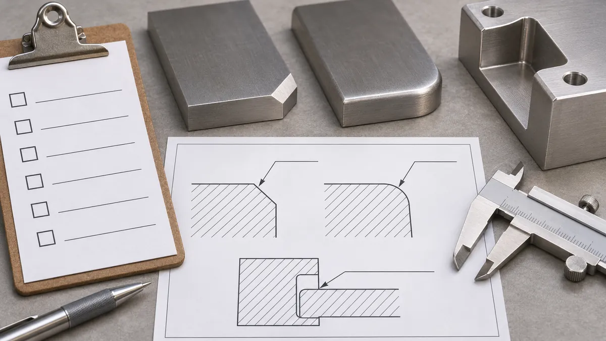
The drawing should identify the affected edge, profile, dimensions, tolerances where necessary, neighboring features, finish requirements and acceptance basis. A useful specification lets the supplier understand the intended geometry and lets the buyer inspect the relevant result without inventing missing details.
How should buyers compare chamfers and fillets?
A chamfer is a flat, sloped transition cut or formed along an edge. A fillet is a curved transition between neighboring surfaces.
What should the drawing specify for an edge feature?
Mark the exact edge or edges
Identify the edge by view, detail, section, model annotation or another controlled reference. A part may have many edges; “chamfer all edges” can create unintended changes to mounting surfaces, holes, cosmetic boundaries or mating faces. If only selected edges need treatment, mark them explicitly. If an edge is excluded, state that too when ambiguity could affect fit or finish.
Distinguish internal and external transitions. An internal corner may have a different access or material-removal constraint than an exposed outside corner. A bend line, cut edge, hole entrance and welded intersection are not necessarily equivalent features. Include a detail view when a general view does not show the edge clearly.
Define dimensions and measurement conventions
Define dimensions and measurement conventions
For a chamfer, specify the angle and relevant setback dimensions, or use another clearly defined callout accepted by the design and manufacturing teams. For a fillet, specify the radius or required range and identify how tangent transitions should continue if that matters. State units and the drawing revision. If edge variation is allowed, define it rather than relying on an undocumented shop convention.
Avoid copying one standard angle or radius from an unrelated part. A fastener entrance, decorative shelf edge, tube end and mounting plate can have different functions. A nominal model dimension may not capture the final finish build-up or material removal. Decide whether the dimension applies before or after finishing, and document the relevant inspection condition.
Connect the profile to the mating assembly
Show adjacent surfaces, clearance envelopes, fastener paths, inserts, covers and any component that contacts the edge. If the edge supports a lead-in, identify the part being guided and the direction of assembly. If clearance is the concern, state the mating dimension and allowable fit. A chamfer can remove material from a corner; a fillet can occupy space near the corner. Either could alter clearance depending on the geometry.
For bathroom and home-storage hardware, the feature may sit near a mounting plate, bracket, hook, tube, wire end or decorative cover. Do not assume an edge can be modified without affecting wall spacing, screw access, assembly order or finish appearance. A sample review should use the actual adjoining parts rather than considering the edge in isolation.
State the finish and cosmetic inspection zone
Polishing, coating, plating or other finishing steps can change how an edge appears and may make a small profile harder to inspect. Define the required appearance of visible edges and the reference sample if consistency matters. Specify which faces are cosmetic and how the part will be viewed. A smooth-looking finish does not prove that a dimensional radius or bevel meets the drawing.
If the edge treatment is intended to reduce a burr, specify the acceptable condition and relevant inspection method. Do not assume that a coating hides an unacceptable burr or that any visible bevel satisfies a dimensioned chamfer. Where a buyer needs both a defined geometry and a controlled surface, specify both requirements separately.
The route affects how an edge is produced, reached and inspected, so a drawing should define the feature before a supplier commits to a process or quotation. The same nominal geometry may be approached differently on sheet, wire, tube, a machined component or a welded assembly. This article does not assign one method or factory capability to every part.
For a machined part, a cutter, tool path, internal corner and tool access can influence the feasible profile. Protolabs’ design explanation of fillets and chamfers discusses these features in the context of CNC machining. Its specific service guidance should not be treated as a universal cost rule for all factories or processes.
For formed sheet or wire, an edge may result from cutting, bending, stamping, grinding or a purchased component. A drawing’s modeled fillet may not correspond to an operation the supplier uses in production. Ask what the feature represents and how the supplier plans to achieve the approved result. If a process change is proposed, verify the actual geometry and function against the drawing and sample.
For welded assemblies, distinguish a part-edge radius from a fillet weld callout. The weld location, size and appearance criteria need their own definition. Grinding a weld or adjacent edge can affect material and visible finish; do not imply that a larger bead or smoother transition proves structural performance. If the joint is important to function, obtain the applicable engineering and inspection requirements.
Thin materials deserve particular attention when a chamfer, radius or edge break removes material near a hole, bend or mating feature. A geometric edit may affect available section, coating coverage, edge distance or part fit. This is not a claim that every small chamfer weakens a component. It is a reason to review the actual drawing and intended function before changing a feature late in the process.
| Which edge is affected? | Mark exact location and excluded edges | Prevents treating every corner as identical |
|---|---|---|
| What profile is required? | Flat bevel or curved transition, with a clear callout | Distinguishes geometry before process selection |
| What dimensions control it? | Angle/setbacks or radius, units and tolerances as needed | Makes quotation and inspection more consistent |
| What does it mate with? | Adjacent part, assembly direction and clearance | Connects the feature to the real product |
| What finish applies? | Cosmetic faces, finish reference and before/after condition | Avoids confusing appearance with geometry |
| What evidence is needed? | Sample, dimensional check or other specified review | Limits conclusions to what was actually verified |
How can buyers inspect chamfers and fillets on a sample?
Inspect the sample against the same drawing revision, edge locations and acceptance basis used in the quotation. Confirm the profile and dimensions that matter, then check the mating assembly and visible finish. A photograph alone may hide the transition, scale and surface condition.
Begin with document alignment. Confirm the sample ID, drawing revision, material/finish description and supplier’s stated manufacturing approach. If a supplier changed the callout, ask for a revised drawing or written deviation. Do not accept a verbal “same as sample” when the sample itself has no traceable specification.
Use a suitable measuring method for the required feature. A visual check can identify a clearly flat or rounded profile, but may not establish a small radius or angle accurately. A template, gauge, optical measurement or other method may be appropriate depending on the design and tolerance; the project should specify the method when measurement precision matters. This guide does not prescribe a universal gauge or tolerance.
Then assemble the mating components. Check that the feature does not interfere with a fastener, cover, wall-facing surface or adjacent part, and that the expected assembly sequence is possible. Record whether the review was visual, dimensional or functional. A fit check cannot automatically prove strength, fatigue behavior, safe handling or long-term performance.
For a finished sample, evaluate the edge in its final state. Confirm the intended appearance, coating continuity if that is a requirement, and any exposed burr or surface issue identified by the project specification. Do not conclude that a polished or coated edge has the right underlying radius simply because it appears smooth. Where a test or acceptance criterion is needed, define it before evaluating the sample.
| Edge location | Drawing view and exact feature checked | Does not prove unmarked edges were controlled |
|---|---|---|
| Profile | Chamfer, fillet or specified edge break observed | Visual observation may not establish dimensions |
| Dimension | Measurement method and result where required | Applies only to the measured location and method |
| Mating fit | Parts and revision assembled; interference notes | Does not prove structural performance |
| Finish | Approved reference and cosmetic faces reviewed | Appearance does not prove hidden geometry |
| Change record | Deviations, responsible reviewer and disposition | Approval applies only to recorded revision/scope |
Ambiguity usually appears when a design intent is expressed as an undocumented manufacturing assumption. The buyer can prevent avoidable back-and-forth by separating the desired shape, its purpose, dimensions and acceptance evidence.
What mistakes create ambiguous edge requirements?
Deburring removes or reduces burrs according to a defined requirement; it does not automatically tell the supplier to create a particular chamfer or radius. If the edge geometry controls fit, appearance or assembly, give the feature a specific callout. If the intent is only to remove a burr, define the acceptable edge condition and affected locations.
Assuming every chamfer is 45 degrees
Some equal-distance chamfers on perpendicular faces produce a 45-degree transition, as Shapr3D’s documentation explains for that setting. Other chamfers use unequal setbacks or different geometry. Do not let a common example become an unapproved default on a production drawing. State what is needed for the actual design.
Assuming a fillet always improves strength
A rounded transition changes local geometry, but it does not establish the performance of the whole component. Material, section, loads, manufacturing, joints and boundary conditions matter. Any structural conclusion needs an appropriate design basis and evidence. Avoid blanket claims that a fillet always increases strength or a chamfer always weakens a part.
Treating the CAD model as proof of production capability
A model can communicate a desired shape, but its presence does not confirm tooling access, tolerances, finish or inspection. Ask the supplier to review the model and drawing and identify any unclear or infeasible detail before quotation. Record any proposed change for the design owner to approve.
Confusing the edge fillet with a fillet weld
The same word appears in two technical contexts. A fillet weld refers to a weld/joint type; a fillet edge is a rounded transition between surfaces. Use a weld symbol and edge-radius callout in their respective contexts so that a supplier does not confuse a joint requirement with a part-edge requirement.
Inspecting only the best-looking edge
One corner may be easy to access while another is hidden or intersected by a joint. If several edges are critical, identify a representative sampling plan or inspection scope. Do not extrapolate one measurement to every edge without an agreed basis.
How can a small-batch OEM factory help clarify an edge callout?
A specialized OEM manufacturer can review a drawing or physical sample, identify missing edge information and explain which manufacturing details need clarification within the confirmed project scope. Koitor Hardware is a family-owned custom metal hardware manufacturer serving bathroom and home-storage product development. The useful review is tied to a specific component and approved drawing, not a general claim that every radius, chamfer or machining operation is available in-house.
For small-batch development, share the part drawing, assembly view, material and finish, required quantity, sample goal and any mating component. Highlight the exact edges and explain whether they are cosmetic, functional or simply need a defined edge condition. This allows the supplier to identify questions about access, finishing, joining, assembly and inspection before parts are quoted.
When the factory proposes an alternative, request the revised section or drawing, dimensions, process assumption, finish impact and reason for the change. A proposed edge break may be sensible for manufacturing, but the buyer or design owner must decide whether it preserves product requirements. The change should be recorded against the correct revision, and a sample may be needed when the visual or mating result matters.
Koitor’s role is to communicate directly about custom metal hardware fabrication, drawing/sample review, assembly, finishing clarification and packaging within its verified scope. Exact CNC machining, radius control, tooling or tolerance capability is project-specific and should not be presumed from a general product description. If a feature depends on a purchased component or outside process, identify the responsible source and the evidence the buyer needs.
Small-scale production flexibility can help with trial orders and product development, but it does not replace controlled specifications. Define the feature before the sample is approved, document the accepted result and state what changes require notification. This helps keep a small trial and a later reorder aligned without suggesting that one sample alone guarantees every future part.
Buyer checklist before approving an edge detail
Use the checklist to close the drawing and sample review. It deliberately leaves room for a buyer to mark a requirement as open and assign an owner instead of guessing.
- Part and revision: identify the component, assembly and controlled drawing revision.
- Edge location: mark each affected edge and explicitly identify exceptions.
- Geometry: state whether the feature is a chamfer, fillet or a defined deburr/edge break.
- Dimensions: give angle and setback(s) or radius, plus units and tolerances where required.
- Purpose: state fit, lead-in, appearance, clearance or other intended function.
- Interfaces: identify mating parts, fasteners, assembly direction and required clearance.
- Material and route: record the specified material and ask the supplier to confirm the intended process scope.
- Finish: identify cosmetic faces, finish reference and whether dimensions apply before or after finishing.
- Inspection: state what is measured, where, by what method and against which criterion.
- Sample: trace the accepted edge to a revision and record any deviations or open questions.
- Change control: require review before substituting a chamfer, radius, process or edge condition.
- Quotation: ask the supplier to disclose assumptions, exclusions and any feature requiring clarification.
For an RFQ, a marked section view and one clear comparison example are often more useful than several ambiguous phrases. If the feature does not yet have a critical dimension, say so and ask the designer to decide whether visual guidance is sufficient or a measurable limit is needed. The buyer can then compare quotations on the same defined scope.
Frequently asked questions about chamfer vs fillet
Is a chamfer always 45 degrees?
No. A 45-degree bevel can result from equal setbacks on perpendicular faces, but chamfers can be asymmetric or use another angle. Specify the actual edge geometry needed rather than assuming a default.
Does a deburr note mean the edge has a particular radius?
No. A deburr or edge-break instruction needs an applicable definition and acceptance basis. It does not automatically set a chamfer dimension or fillet radius. Add a specific callout when controlled geometry matters.
Which is stronger, a chamfer or a fillet?
There is no universal answer based only on the profile name. Structural performance depends on the material, dimensions, loading, joints and manufacturing condition. Use an appropriate design review and evidence for the actual product.
Is a fillet weld the same as a fillet edge?
No. A fillet weld is a weld/joint term; a fillet edge is a rounded transition between adjacent surfaces. Keep weld symbols and edge-geometry callouts distinct on the drawing.
Can the manufacturer choose a radius from the CAD model?
The model may show design intent, but the buyer should confirm the controlling drawing, dimensions and tolerance. Ask the manufacturer to identify any process limitation or suggested deviation and obtain approval before the design changes.
How do I check a small chamfer or fillet?
Use a measurement method suitable for the required tolerance and identify the edge location. Visual review may distinguish broad profiles but may not establish a small dimension. Record the method and result, then check the mating assembly if fit is part of the requirement.
Can the edge feature be changed after a sample is approved?
Treat it as a design or process change. Record the proposed geometry, dimensions, reason, finish and impact, and obtain buyer/design-owner approval. Revise the controlled documents and sample record as needed.
Clarify an Edge Detail Before Your Next Hardware Sample
Share the marked drawing or sample, material, finish, mating components and target quantity so the geometry and manufacturing questions can be scoped together.
OEM / PRIVATE LABEL
Turn this sourcing guide into a product brief
Share your target product, size, finish, order quantity and packaging requirements. Your team receives a practical manufacturability review before quotation.
 English
 Español
 Português
 Français
 Deutsch
 العربية