
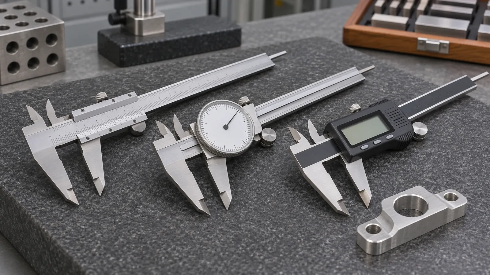
Types of calipers are easier to compare when the readout is separated from the contact geometry and feature being measured. Vernier, dial and electronic or digital describe common ways to read a sliding caliper; offset, blade, reduced-point and other special jaws describe how its measuring faces reach a feature. Inside, outside, step and depth measurements are functions supported by particular instrument configurations. A digital display is not a universal accuracy ranking. Before specifying an inspection method, match the model, range, reach, contact faces and measurement plan to the actual part feature.
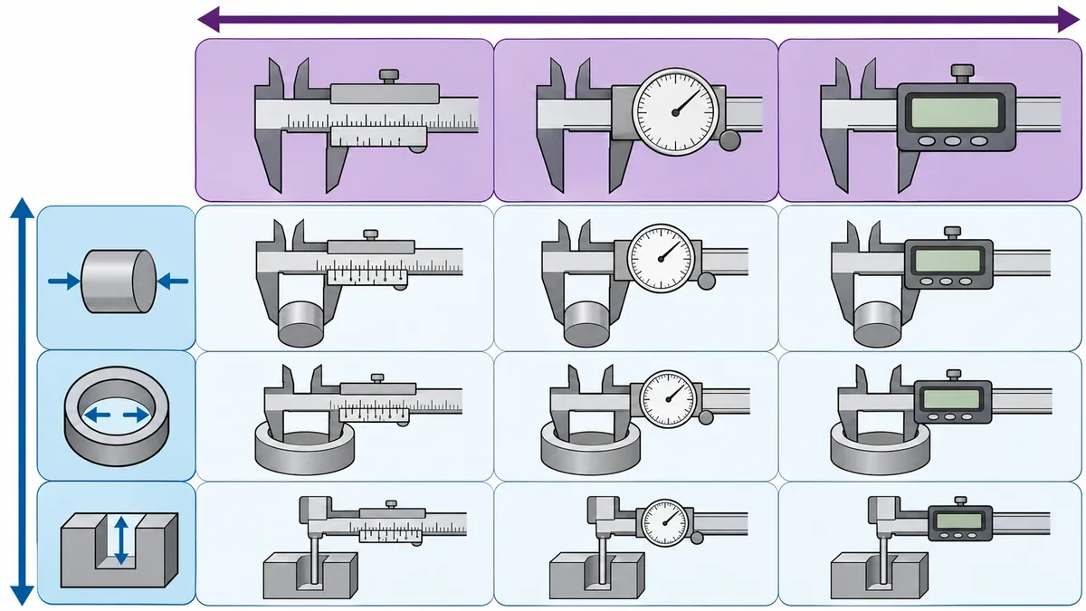
Types of calipers by readout
For general slide calipers, three common readout families are vernier, dial and electronic or digital. Each communicates a measured slider position in a different way. A vernier uses a main scale and a subsidiary vernier scale; a dial caliper uses a mechanical dial with the beam scale; an electronic caliper presents a sensed position on a display. These describe the readout, not three guaranteed levels of accuracy or suitability.
The instrument maker Mitutoyo’s Product Fundamentals bulletin describes vernier, dial and electronic caliper readouts and separately discusses measuring faces and special jaw designs. That separation is useful for buyers: how the measurement is displayed is only one part of selecting an instrument. Model specifications, range, resolution, jaw condition, environment, measurement method and the part itself still matter.
| Readout family | How the reading is presented | Buyer questions |
|---|---|---|
| Vernier | Main scale read with a sliding secondary scale | Can the intended inspector read and record the scale consistently? What model specification applies? |
| Dial | Mechanical pointer and dial combine with a beam scale | Is the dial easy to view in the measurement position? What model and range are specified? |
| Electronic or digital | A display shows the slider position from an electronic sensing system | What model-specific specification, units and environment apply? How is the reading recorded? |
This table is a classification aid, not an accuracy comparison. A manufacturer can offer multiple models within each family, and specifications can differ by model. Do not use a generic chart to claim that one display family is always more accurate, durable, inexpensive or suitable. Compare the actual manufacturer specification for the instrument selected and the measurement task it will perform.
Does digital mean a caliper is always more accurate?
No. Digital describes the readout style. Accuracy, resolution, repeatability, measurement uncertainty and environmental suitability are separate properties that must be assessed using the actual instrument specification and measurement plan.
Caliper jaws and contact geometry
Jaw geometry is another classification axis. A caliper can have ordinary outside and inside jaws, or purpose-designed contacts such as offset, reduced-point, blade or other special jaws. A special jaw may be paired with a vernier, dial or electronic readout. The readout and the geometry can vary independently.
Outside jaws contact the external surfaces of a part. Smaller inside jaws can reach some internal openings, but a particular throat, recess, wall or tube may be inaccessible or difficult to contact consistently. Depth features may be assessed with a depth rod or another designed feature. Step measurement relies on appropriate faces and access to the relevant surfaces. The actual manufacturer’s model and jaw shape determine what can be measured; a tool’s general caliper label is not enough.
Special jaws address particular access conditions. Offset configurations can reach features that are displaced from a standard jaw contact. Reduced-point jaws may contact smaller features. Blade-style jaws can enter some narrow slots or grooves. Other specialized designs may be intended for compliant materials or unusual part geometry. These descriptions are qualitative; they do not guarantee a measurement result or establish that a jaw can reach every recess of a nominal dimension.
| Geometry or measurement function | What the buyer is trying to reach | What to verify before using the tool |
|---|---|---|
| Outside jaws | External width, thickness or outside diameter | Contact-face condition, part access, stable alignment and applicable model range |
| Inside jaws | Internal opening or inside diameter | Jaw reach, opening geometry, contact position and method suitability |
| Depth feature or rod | Depth from a reference surface | Reference-surface stability, access, orientation and instrument design |
| Step measurement faces | Difference between adjacent levels | Access to both reference faces and consistent seating |
| Offset jaws | Features that are displaced or obstructed | Actual jaw offset and clearance in the part |
| Blade or reduced-point jaws | Narrow slots or small local features | Tip shape, contact area, reach and model-specific instructions |
| Low-force configuration | Features that may deform under contact force | Manufacturer’s intended use and approved method for the material |
The table does not prescribe a tool for a particular component. The feature drawing and instrument manufacturer’s model data must govern. If the contact geometry changes the way a dimension is defined or contacted, document the method so different inspectors do not use different points.
Can a special-jaw caliper also be digital?
Yes. Readout and jaw configuration are separate attributes. A special-jaw design can be offered with a particular readout, depending on the manufacturer’s catalog. Confirm the exact model and intended feature.
Measurement functions are not readout types
Outside, inside, step and depth describe the kind of feature or dimension being checked, not the display family. A digital caliper may support several functions, while a vernier or dial model can also be configured for particular measurements. Whether a specific tool can reach a specific feature depends on its construction, length, jaw shape and manufacturer’s intended use.
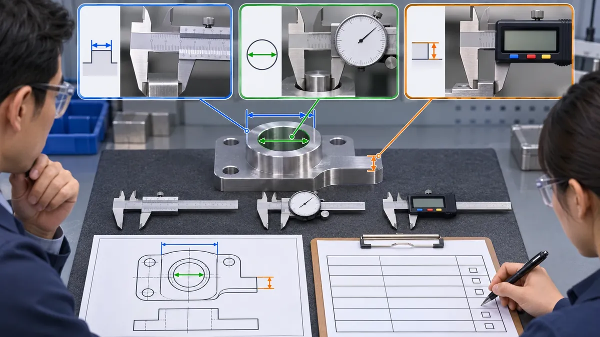
This distinction prevents vague inspection instructions. A drawing note that says “check with caliper” does not state which surfaces to contact, where the measurement is taken, how the part is positioned, or what the result should be compared against. For a formed bracket, the inspector may need to check an outside width at a defined location, an inside opening between surfaces, a step from a datum or a feature depth. The drawing or inspection plan should identify the controlling surfaces and measurement location.
Some features are poor candidates for a general caliper method. A thin compliant part may deflect under contact; a narrow recess may not admit the jaws; a curved or irregular surface may not provide stable contact; a deep feature may exceed reach; and a small internal diameter can require a different instrument or method. These observations are reasons to assess the method, not a claim that a caliper can never be used. The responsible quality or engineering owner should select an appropriate instrument based on the dimension and acceptance need.
A readout can make a value easier to display, but it does not automatically fix poor alignment, inconsistent contact, parallax, operator technique, part temperature, surface contamination or an unsuitable feature definition. The measurement process has to address the actual sources of variation that matter to the decision.
Choose a caliper for the actual feature
Start with the dimension and drawing, not with a preference for digital, dial or vernier. Identify the two surfaces or reference points that define the feature. Then determine whether the caliper can contact them without obstruction, tilt or excessive force. Confirm the required range and whether the jaws provide enough reach.
For a metal hardware bracket, a digital caliper may appear convenient, but the display alone does not establish that its jaws can contact the bottom of a recessed slot or bridge an irregular edge. The buyer or inspector should determine whether the measurement is an external width, an opening, a step or a depth and specify the exact contact position. If the point of contact is not defined, two inspectors can obtain different readings while both believe they followed the same general instruction.
A tool selection record can include:
- The part number and drawing revision.
- The feature ID and nominal dimension.
- The datum or surfaces to contact.
- The caliper model and readout family.
- The jaw configuration and range needed.
- The measurement orientation and access condition.
- The required record, units and review responsibility.
- Any alternative method approved for inaccessible features.
Do not add a tolerance that the drawing or design owner has not specified. A caliper is an instrument; it does not define product acceptance. If the dimension is near an acceptance boundary or the method is not suitable, the quality team should review whether another instrument, fixture or method is needed. This article does not provide a calibration procedure, measurement uncertainty calculation or numeric acceptance limit.
What should be checked before using a caliper on a narrow recess?
Confirm that the model’s jaws can reach the intended surfaces, that the contact faces are appropriate and that the drawing defines the measurement location. Do not assume a standard jaw can measure a feature simply because the display can show a value.
Read model specifications without generalizing
Once the measurement geometry is understood, compare actual instrument data. Review range, jaw dimensions, contact design, display, units, stated performance specification, environment and the manufacturer’s instructions for use. These vary by model. Avoid copying a value from one catalog into a generic comparison between vernier, dial and electronic families.
The word “resolution” refers to the smallest displayed or indicated change under a particular instrument specification; it is not the same as accuracy or measurement uncertainty. A display that shows more digits does not, by itself, establish that the measured value is closer to the true value or that a product should pass inspection. The relevant technical terms and definitions need to be applied according to the applicable specification and quality system. If a buyer needs a decision rule, the responsible quality authority should define it.
A high-level instrument comparison can look like this:
| Selection dimension | Questions for the buyer or inspector |
|---|---|
| Readout | Which display can the team read, record and review consistently? |
| Range | Does the model cover the feature and the required measurement span? |
| Reach | Can its jaws or probe contact the defined surfaces? |
| Contact design | Are the faces appropriate for the shape, material and feature size? |
| Environment | Does the instrument manufacturer specify use restrictions relevant to the inspection area? |
| Documentation | What model data, calibration status or records does the quality plan require? |
| Method | Are datum, orientation, contact points and units described? |
| Decision rule | Who determines whether the result meets drawing requirements? |
This is a review framework, not a ranking. Model choice should be based on the actual feature and quality plan. A lower-cost tool may be adequate for one non-critical check but unsuitable for another; a specialized instrument may be necessary where access or measurement uncertainty requires it. The article does not make product endorsements or set a universal instrument hierarchy.
During supplier audits, ask the inspection team to identify the instrument actually used for a reported result, not merely the general tool category. A record that says “digital caliper” may still omit the model, range, jaw configuration, instrument status or measurement location. The level of detail needed depends on the buyer’s quality requirements, but the record should be sufficient to explain how the result was obtained and which feature was checked. If the inspection is not a formal acceptance activity, label it accordingly so a screening observation is not mistaken for a certified or final measurement.
Are inside and outside measurements different caliper readout types?
No. They describe measurement functions or feature geometry. A vernier, dial or digital readout can be paired with different measuring faces, subject to the model’s design and intended use.
Avoid common caliper selection mistakes
Ranking the readout families by accuracy. No family name establishes universal accuracy. Use model-specific evidence.
Confusing resolution with accuracy. Display increments do not prove that a measured value meets a product tolerance.
Selecting a tool from a product photo. The image may not reveal jaw reach, measuring faces or clearance around the actual part.
Assuming all calipers measure every feature. Range, jaw geometry, reach and access can limit a method.
Treating inside, outside, step and depth as mutually exclusive tool types. These are measurement functions; the readout classification is separate.
Using “measure with calipers” as the complete inspection instruction. Identify contact surfaces, location, orientation, units and acceptance criteria.
Assuming a special jaw changes only convenience. Different contact geometry can change how the feature is accessed. Confirm that the method still measures the intended dimension.
Using a hand-fit or visual check as a formal inspection result. It may help with initial identification but should not replace the approved method when formal acceptance is required.
Claiming calibration from a tool type. Vernier, dial or digital does not establish calibration status. Review the instrument’s records under the applicable quality system.
Buyer checklist for selecting a caliper method
Before adding a caliper check to an incoming, in-process or final inspection, document:
- The part and controlled drawing revision.
- The exact feature and nominal dimension.
- The surfaces, datum and location to contact.
- Whether the task is outside, inside, step or depth measurement.
- The required range and reach.
- The caliper readout family and model.
- The jaw geometry and contact faces.
- The manufacturer’s model-specific specification and use instructions.
- Units, measurement orientation and recording format.
- The applicable inspection plan, review owner and acceptance decision.
- How instrument status and required records are controlled.
- What alternative method is approved if the feature is inaccessible.
For a special feature, have the tool and method reviewed on the actual part or a representative sample before inspection begins. The review should confirm that the contacts land on the intended surfaces and do not damage or deform the component. It should also state what the check does not prove. A single caliper reading may not establish an entire profile, roundness, flatness, surface finish or full product performance.
Using types of calipers in an inspection handoff
An inspection handoff should connect the drawing, feature and instrument method. Identify the part number and revision, feature identifier, nominal dimension and the contact surfaces. State whether the check is outside, inside, step or depth, and note the tool model or permitted model range if the method is already approved. Add the units and where the result is recorded. If the part is difficult to access, include a small drawing detail or photograph that shows the measurement location, while keeping the controlled drawing as the authority.
The handoff should also distinguish a screening check from final acceptance. A buyer may use a caliper to compare a sample or incoming component against a simple dimension. A formal acceptance check may require a defined sampling plan, calibrated instrument status, specified tolerances and review by the quality function. The person writing the note should not assume that the readout automatically establishes all of these controls. Refer to the project inspection plan for details instead of embedding unapproved tolerances in a tool description.
When a supplier cannot measure a feature with the proposed caliper, record the limitation and ask for an alternate method. The alternative could require a different contact, a fixture or another measuring instrument, but the choice belongs to the responsible quality or engineering owner. Document what changed and keep the original drawing requirement intact unless the design authority approves a revision. This makes the inspection result easier to interpret later and prevents a convenient tool from redefining the product dimension.
For repeat inspections, use the same feature definition and contact points. If the instrument model changes, verify that the new tool still reaches the required surfaces and meets the quality plan. The readout can be different while the measurement definition remains the same, but that should be confirmed rather than assumed.
What Koitor can clarify in a hardware inspection discussion
Koitor is a family-owned custom metal bathroom and home-storage hardware factory supporting buyer drawings or samples and relevant forming, joining, finishing, assembly and packaging work. These approved facts do not establish a metrology laboratory, calibration service or ownership of any specific inspection instrument.
If a buyer wants to discuss a dimension on a custom metal product, provide the current drawing, the feature of concern, the inspection location and the acceptance requirement. Koitor can review the product and manufacturing context within its stated scope and identify where a measurement method needs clarification with the buyer’s quality team. The buyer or responsible quality authority defines the acceptance criteria and evidence required.
A well-defined inspection note helps suppliers and buyers discuss the same feature. It can distinguish a width from an opening, an external face from an internal contact and a readout preference from the actual measurement requirement. It does not replace the instrument maker’s model instructions or the buyer’s quality system.
Frequently asked questions
What are the three common caliper readout types?
Common general-purpose slide-caliper readouts include vernier, dial and electronic or digital. Each describes how the reading is displayed. The actual instrument model and its specification determine its capabilities.
Are digital calipers more accurate than dial calipers?
Not as a universal rule. Compare the selected models and the measurement task. Readout family alone does not establish accuracy, resolution or uncertainty.
Can calipers measure an inside diameter?
Some calipers have inside jaws for certain internal features. Access, geometry, range and model-specific method matter. A drawing or quality plan should identify how the dimension is measured.
What are special-jaw calipers used for?
Special jaw configurations can access particular features or contact surfaces. The intended use depends on the specific jaw and model. Confirm fit against the actual part and the manufacturer’s instructions.
Should buyers use a caliper for every metal hardware dimension?
No. The tool and method should suit the feature and acceptance need. Some dimensions may require another instrument, a fixture or a different inspection method.
Work With Koitor Hardware
If a metal hardware drawing contains a feature that is difficult to inspect, share the controlled drawing or sample and the dimension under review. Koitor can clarify the product geometry and manufacturing context within its OEM scope. The buyer’s quality team remains responsible for selecting the measurement instrument, method and acceptance criteria.
Clarify a Hardware Measurement Feature
Send the current drawing or sample, the dimension in question and the inspection requirement. Koitor can review the metal hardware context while your quality team approves the measurement method.
OEM / PRIVATE LABEL
Turn this sourcing guide into a product brief
Share your target product, size, finish, order quantity and packaging requirements. Your team receives a practical manufacturability review before quotation.

 English
 Español
 Português
 Français
 Deutsch
 العربية