

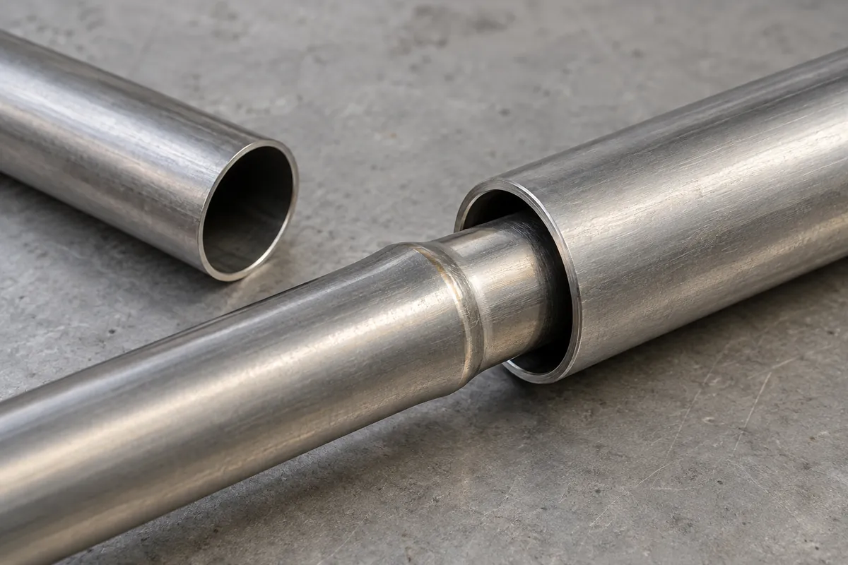
Tube end swaging fit should be specified as a mating-interface requirement, not merely as a request to “reduce one tube end.” For a storage rack or tubular frame, the buyer should define the original tube and receiver, reduced-end dimensions and length, transition profile, assembly condition, finish allowance, and whether the joint is intended to slide, locate, or resist separation. A production-intent sample should confirm the finished, coated fit before the drawing and inspection plan are released.
What does the joint need to do?
Begin with function. A reduced tube end may make two frame members nest for shipping, let an upright engage a crossbar, align a modular rack, or create a telescoping connection. Those functions place different demands on the interface. A joint that only locates parts during assembly is not automatically a load-bearing lock. A slip fit is not automatically a retention feature, and engagement alone does not establish structural capacity.
Write the assembly sequence in plain language: which member enters which receiver, from which direction, how far it is inserted, and whether the user or factory should be able to remove it without tools. Record whether the assembled rack is expected to be fixed, adjustable, collapsible, or repeatedly disassembled. These use conditions guide the drawing and sample review. They also prevent a supplier from inferring a locking feature where the buyer only intended alignment—or the reverse.
For a storage product, the surrounding construction matters. A tube may connect to a welded wire basket, a formed bracket, a plastic foot or a second tube. Each adjacent component can constrain access, insertion depth and assembly order. If the joint sits behind a shelf or inside a sleeve, the buyer should identify those relationships in the drawing or assembly model. A tube-end detail viewed alone may hide a collision or leave no practical way to inspect insertion depth.
A useful requirement separates four questions: does the part fit, does it reach the intended position, does it remain in that position during the specified handling, and does the finished product meet its intended use requirement? A simple fit sample answers only the first few. Load, stability and service qualification require their own agreed method and must not be inferred from a swage drawing.
Treat tube end swaging fit as a drawing-and-sample decision shared by engineering, sourcing and supplier quality. Each reviewer should be able to point to the same mating parts, revision and assembly behavior rather than rely on an informal verbal description.
Which dimensions belong on the drawing?
The drawing should identify both sides of the interface. For the parent tube, specify the relevant outside dimensions and wall or material-form requirements already controlled by the product specification. For the receiver, identify its internal opening or effective mating surface, shape, orientation and any feature that limits insertion. Do not rely on a single nominal tube size if the connection uses an oval, rectangular or otherwise non-round profile.
For the reduced end, define the formed length and the usable engagement length separately when they differ. Call out the end profile, reduced outside dimensions, transition length or shape, and any end condition that affects insertion. If the interface needs a stop or shoulder, show how that stop is created and where it contacts the receiving member. A broad note such as “swage to fit” leaves the supplier to choose what fit means.
| Drawing item | Why the buyer should define it | Sample-review question |
|---|---|---|
| Parent tube profile and material form | Establishes the starting geometry and relevant variation | Does the sample match the specified tube section? |
| Reduced-end dimensions | Controls the mating envelope | Does it enter the actual receiver without forced deformation? |
| Formed length and engagement | Determines insertion depth and contact area | Does the assembled part reach the intended position? |
| Transition shape | Affects insertion, appearance and local geometry | Is the transition free from an unacceptable abrupt shoulder or damage? |
| Stop or retention feature | Separates simple location from positive retention | What prevents movement, if retention is required? |
| Finish and coating condition | Changes the final mating interface | Was fit checked after the specified finish? |
| Inspection datum and method | Makes production checks repeatable | Can the supplier measure the critical region consistently? |
The tolerances must be developed for the actual geometry, material, forming method and assembly requirement. Avoid inserting a generic clearance or reduced diameter from another product. The buyer and supplier should identify the critical-to-fit dimensions and agree how they will be measured, including where the measurement starts and whether the part is tested before or after finishing.
If a design uses a round tube entering a round receiver, nominal diameters alone may still miss ovality, local flattening or springback. For shaped tube, define orientation as well as dimensions. If the joint must align a shelf or crossbar, include a rotational datum or visual orientation feature. Otherwise a part may slide into the receiver but assemble in the wrong direction.
How should buyers distinguish a slip fit from retention?
A slip fit is an assembly relationship that allows insertion with the intended effort. Retention is a separate behavior: the connection resists withdrawal or movement under a stated condition. Buyers should avoid using “tight fit” as a substitute for a measurable requirement. It can mean difficult hand assembly to one reviewer and loose engagement to another.
If the joint is intended to be removable, specify the desired assembly and removal behavior using a defined sample or approved reference, plus any measurable dimensions the supplier can control. If the connection is intended to stay assembled, identify what mechanism provides that function—such as a shoulder, detent, fastener or interference—and define the inspection or test relevant to it. The actual design must determine which mechanism is appropriate; the phrase “swaged end” alone does not identify one.
For telescoping members, distinguish adjustment travel from final retention. A buyer may need smooth movement over a range but no unintended separation at the extension limit. That can require a stop or other feature beyond the reduced tube end. A sample that moves smoothly on the bench does not prove it will behave acceptably in the complete rack or after repeated use.
Do not assign an unverified load rating based only on the fit of two tubes. If the assembled frame will carry a defined load, the product team should create a separate qualification method for the complete structure and its intended configuration. The tube connection, welds, supports, fasteners and floor contact all contribute to overall behavior. A swage interface can be inspected for fit without being represented as a standalone structural test.
What should the production-intent sample prove?
Ask for a sample made with the intended tube material form, forming route, tooling approach and finish sequence, or have the supplier clearly mark any differences. A hand-adjusted prototype can help evaluate concept and ergonomics, but it may not represent repeatable production. Buyers should know whether the sample demonstrates geometry only, process capability, appearance, assembly effort or a combination.
Review the parts as a set. Use the actual mating receiver, not a substitute gauge that omits welds, coating or nearby features. Check the planned insertion depth and orientation. Record whether the joint can be assembled in the intended sequence and whether adjacent shelves or brackets block access. A few photographs with reference points can make approval easier to communicate across sourcing, engineering and supplier quality.
The sample should also reveal the transition area. Look for cracks, splits, wrinkles, sharp edges, visible tool marks or a profile that departs from the intended appearance. These observations should be judged against the drawing and finish standard, not a vague expectation of “perfect.” If the part is coated or plated, inspect the final interface condition and confirm whether the coating accumulates where the tubes mate.
Use a sample record with revision, material declaration, process notes when available, finish condition, mating part, observations and disposition. If the buyer requests a change—such as more engagement or a different shoulder—update the drawing and sample revision together. Do not let a verbally approved sample silently become the only production definition.
How can finish and tolerance affect assembly?
The final assembly condition matters. Coating, plating, polishing, deburring or other finishing steps can affect dimensions and surface contact. The direction and magnitude of those effects depend on the actual process and geometry; avoid assuming a universal allowance. The specification should identify whether critical dimensions apply before finishing, after finishing or in both states.
Where the receiver is welded or assembled from multiple formed parts, the opening may also change during fabrication. That means a tube-end sample may fit a standalone receiver but not the production assembly. Review the joint in the surrounding structure and identify the condition that is the acceptance reference. If an assembly fixture is used, include it in the approved inspection method only when it represents the intended mating relationship.
A supplier discussion should distinguish normal variation from a design problem. If sample fit varies, ask which dimension or operation is driving the difference and whether the drawing controls it. The corrective action may be a clarified datum, a process adjustment, a revised transition, a finish-stage control or a changed mating feature. Avoid solving a poorly defined interface by asking for tighter tolerances everywhere; that may increase cost without controlling the actual assembly issue.
That distinction keeps tube end swaging fit actionable at the supplier review: the team can decide whether to revise geometry, clarify inspection, adjust the finish allowance or approve the existing sample condition.
For repeat orders, the buyer should define how engineering changes affect the interface. A revised tube wall, receiver, coating, weld location or supplier can alter fit even if the nominal outside dimensions remain unchanged. Link the approved sample and inspection record to the drawing revision and purchase specification.
What should go into the RFQ and inspection plan?
The RFQ should include a drawing or controlled sketch, mating-part information, expected assembly function, finish state and sample approval criteria. State which dimensions are critical to fit and ask the supplier to identify any missing geometry before quoting. If the supplier proposes a forming route or needs production tooling, ask which assumptions affect development time, sample iterations and repeatability. Do not treat a quotation as confirmation that an unstated tolerance or retention behavior has been accepted.
The inspection plan should use a suitable method for each characteristic. A dimensional check may verify reduced dimensions and formed length; a go/no-go fixture may assess a specific assembly interface; visual review may check surface condition. The method must reflect the feature being controlled. A fixture that only confirms insertion should not be described as proof of load capacity or long-term retention.
| Buyer requirement | Evidence to request | Limit of that evidence |
|---|---|---|
| Reduced-end geometry | Dimension report or agreed inspection record | Does not by itself prove full-frame function |
| Assembly fit | Sample assembled with the mating production part | Applies to the sample and stated revision |
| Surface quality | Defined visual criteria and sample images | Does not establish hidden material properties |
| Retention, if required | Agreed test on the relevant joint configuration | Must not be inferred from insertion fit |
| Repeat-order control | Revision-linked records and change notification | Depends on the agreed supplier quality process |
A practical checklist helps keep the review focused:
- – Identify the buyer, product revision and target use of the joint.
- – Show the parent tube and mating receiver on the same drawing or reference.
- – Specify the reduced-end profile, length, engagement and transition.
- – State whether the joint locates, slides, locks or resists separation.
- – Mark dimensions controlled before or after finish.
- – Request a sample made in the stated production-intent condition.
- – Review fit with the actual mating part and assembly sequence.
- – Record the inspection method and its limitations.
- – Keep sample approval tied to the drawing and finish revision.
- – Define how changes to material, tooling, receiver or finish are reviewed.

How can Koitor support the review?
Koitor is a family-owned custom metal hardware manufacturer focused on bathroom and home storage hardware. Its relevant experience includes manufacturing discussions around formed metal components, joining, finishing, assembly and buyer drawing or sample review. That context can help buyers make the connection requirement clearer before production approval. It does not establish that a particular swaging machine, forming tool or capability is available for every project.
For an RFQ, share the tube profile, receiver detail, assembly sequence, finish requirement and target behavior. The supplier can then identify which items are clear, which need a sample check and which require engineering confirmation. Buyers should confirm the actual process, tooling arrangement, material and acceptance plan for the specific part rather than assuming them from a general capability statement.
الأسئلة الشائعة
Does swaging automatically create a locking connection?
Should dimensions be checked before or after coating?
Can a fit sample prove the rack’s load capacity?
What if the receiver is welded after forming?
What should buyers provide for a useful quotation?
For related manufacturing context, see Koitor’s custom metal storage basket manufacturing page و OEM home-storage hardware information. To discuss a project drawing or sample, اتصل بـ «كويتور».
Clarify a Tubular Joint Before Quotation
Share the tube and receiver drawings, finish condition, assembly sequence and intended joint behavior so the sample review can focus on the dimensions that matter.
OEM / العلامة التجارية الخاصة
حوّل دليل التوريد هذا إلى موجز منتج
يرجى إطلاعنا على المنتج المستهدف، والحجم، والتشطيب، وكمية الطلب، ومتطلبات التغليف. وسيتلقى فريقك تقييمًا عمليًّا لإمكانية التصنيع قبل تقديم عرض الأسعار.

 English
 Español
 Português
 Français
 Deutsch
 العربية