
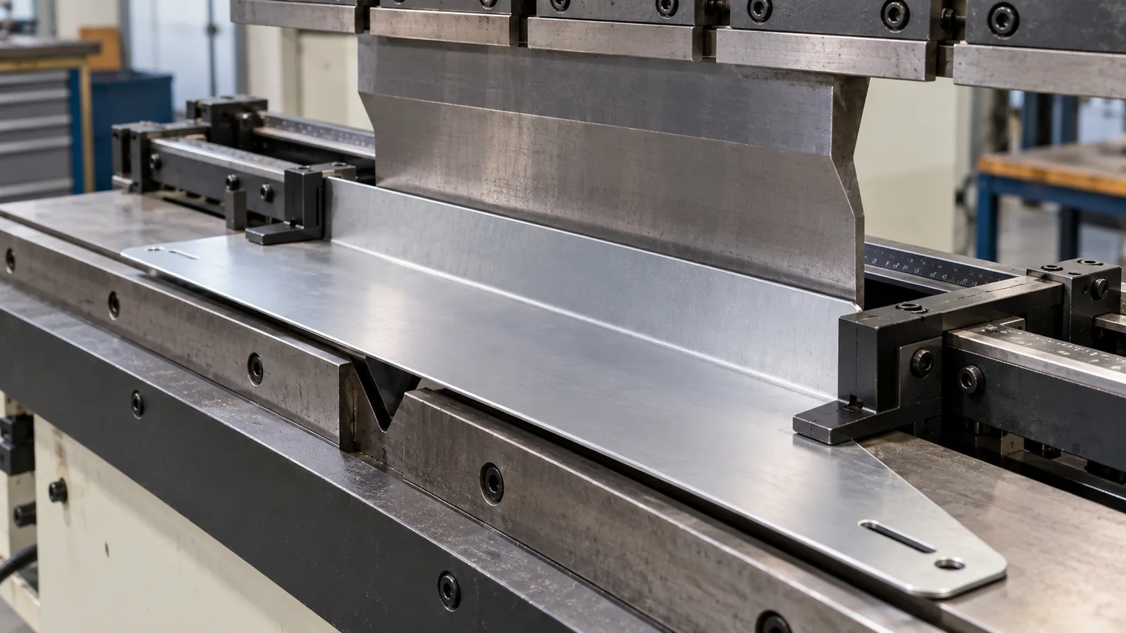
For a long folded shelf bracket, press brake backgauge fingers datum flange skew is a locating and evidence question: which edge contacts the fingers, where the contacts sit along the part, and how the supplier confirms that the resulting flange is aligned to the drawing datum. Buyers should approve that relationship on a representative blank and formed sample—not infer it from a machine photo or a generic press-brake accuracy claim.
A backgauge helps position a workpiece relative to the bend line. Finger shape, contact surface, adjustment, clearance and the part’s bend sequence can influence how the blank seats. If the part touches one finger while rocking away from another, or if the selected edge is not a stable datum, the bend may begin from a different location than intended. That can contribute to skew in the finished flange, but visible skew can also come from blank-edge variation, handling, tooling, material behavior or measurement setup. The first task is to define what moved and when.
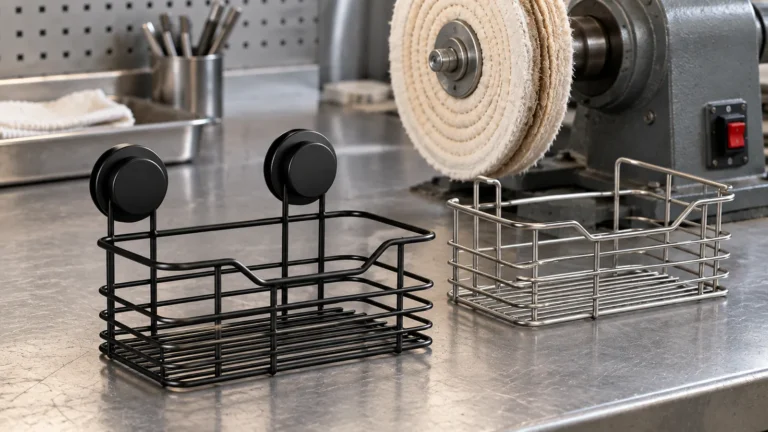
This guide focuses on backgauge contact and datum selection for long folded hardware brackets. It does not replace a separate bend-angle or crowning analysis, and it does not claim a universal tolerance, machine configuration or Koitor-specific backgauge capability. Treat the images as conceptual manufacturing illustrations, not photographs of Koitor-owned equipment or measured production results.
What do press brake backgauge fingers locate?
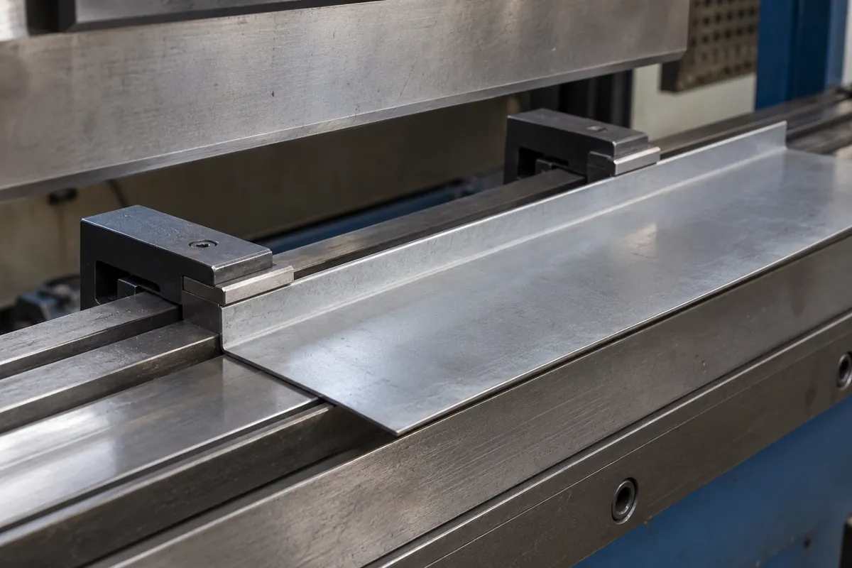
The backgauge fingers create contact points that help position the blank before a bend. The supplier’s setup should establish a repeatable relationship between the chosen workpiece edge, the bend line and the drawing’s functional datum. For a long folded bracket, the question is not only whether the blank reaches the stop; it is whether the part seats consistently without rocking, twisting or contacting an unintended feature.
A finger may have a flat contact face, stepped surface, pin or other geometry suited to a particular part. The right configuration depends on flange shape, clearance, bend order and the physical access required by the tooling. A large contact area is not automatically better if it collides with a previously formed flange or masks a burr. A narrow contact may fit a crowded geometry but require more deliberate verification of where it touches.
ADH’s technical discussion of press-brake stop fingers highlights how finger design and adjustment relate to workpiece location, contact surfaces, available axes or travel, tooling clearance and bend sequence. That is useful background for the buyer’s review. It does not specify a universal finger shape or datum tolerance for a shelf bracket. The supplier must show the actual contact arrangement against the current drawing and part.
The drawing should identify the functional datum and the edge or feature intended to contact the backgauge. A visually straight edge is not necessarily the best datum if it is not controlled or if another feature determines assembly fit. If a bracket mounts to a panel, mates with another metal component or positions screws, connect the datum discussion to that interface. Otherwise, the factory may optimize a convenient edge that does not control the buyer’s actual fit requirement.
For a press brake backgauge fingers datum flange skew review, record the contact points and datum selection separately from angle or profile results. This gives the buyer and supplier a clear way to revisit the locating decision if the flange shifts in a later sample.
Why can a long bracket flange become skewed?
Skew can arise when the part is not located consistently, when the contact points do not represent a stable reference, or when the sequence introduces a different seating condition. It is a symptom with several possible contributors rather than proof that the backgauge alone is faulty.
For example, a blank can have an edge burr or a local cut variation that prevents full, even contact. Two fingers spaced along the length may touch different parts of a slightly irregular edge. A previously bent flange can interfere with the stop or tool, causing the operator to rotate or lift the part to clear it. If only one finger makes contact, the blank may pivot around that point. These conditions can change the starting relationship between the blank and bend line.
The geometry itself matters. A short flange near the ends may seat differently from one that runs nearly the full bracket length. A return or offset can limit access to the finger. A part with several bends may need to be repositioned between operations, so the next bend uses a new edge or feature as its reference. Record the bend sequence and the location used at each operation instead of treating the complete bracket as if it were located only once.
Material and process conditions also deserve a place in the investigation. The approved material grade, thickness range, incoming flatness, surface protection and forming route can affect how a sample behaves. This article does not assume a particular Koitor material or exact part specification. Buyers should use the project’s controlled material documents and ask the responsible supplier what conditions the trial represents.
Inspect the blank before forming, the formed profile after each relevant bend when practical, and the assembled bracket if fit is the actual risk. If the blank edge is skewed before it reaches the press brake, changing finger positions may only hide the incoming condition on one setup. If the blank is square but the flange shifts after a specific bend, review the contact and bend sequence around that operation. Keep evidence tied to the same part and revision.
Which contact approaches should buyers compare?
Ask the supplier to explain the locating approach used for the critical bend and to show how it can be checked. The table below compares review questions rather than prescribing a tooling design.
| Locating approach to review | What the buyer should confirm | Useful evidence | القيود |
|---|---|---|---|
| Two spaced finger contacts on a controlled straight edge | Both contacts seat on the intended datum edge and do not collide with a flange or burr | Setup photo or drawing plus a representative blank showing contact at both points | Two contacts do not correct a poorly controlled or unsuitable datum edge |
| A shaped or stepped contact matched to a formed feature | The feature is stable, accessible and identified on the drawing; the contact does not shift the part | Tool/finger identification and a sample seating check on the actual geometry | A matched contact can be revision-specific and may not suit a changed bend sequence |
| A single contact for restricted access | The locating method prevents unintended rotation and has an agreed secondary check | Sample placement observation and a dimensional or fit check after bending | A single point can allow rotation if the part’s other constraints are unclear |
| A temporary alignment aid or project fixture, if proposed by the supplier | Who owns the fixture, what it references, and whether it is part of the approved production route | Fixture identification, part revision and recorded verification method | A temporary aid is not proof that routine production uses the same location method |
Do not read “two fingers” as a universal requirement. Contact count and shape are tooling decisions for the actual part. The buyer’s job is to specify the functional datum, ask the supplier to identify the contact points and agree on sample evidence that shows the blank seats repeatably. If the supplier changes from one contact strategy to another after approval, determine whether the datum and fit evidence need to be repeated.
How should the datum and sample be specified?
A useful drawing or RFQ should say which feature controls the location and how the critical flange relates to it. Avoid a note such as “keep the bend straight” without identifying the datum, inspection condition or function. If a dimensional tolerance is required, it should come from the product’s design owner and be measurable on the chosen part geometry; do not borrow a generic value from an equipment article.
Include the product and drawing revision, material and thickness as confirmed for the project, blank outline, critical edge condition, bend sequence, functional flange and mating interface. Identify whether the finish is applied before or after forming if that affects the visible surface or measurement. State which faces are cosmetic and which dimensions affect assembly. If the supplier proposes a different datum or contact edge for manufacturing reasons, review the change against the part’s function before sample approval.
The sample record should identify what was made and how it was located. Ask for the actual finger or stop arrangement, the edge or feature contacted, and the operation at which the contact is used. A clear setup photograph can help explain access and contact, but a photograph alone cannot demonstrate a dimensional result. Pair it with the agreed inspection or fit evidence.
For a long bracket, measure the relationship that matters along its length, not only at a convenient end. The drawing may specify a profile, flange relationship, hole location or assembly condition. The measurement plan should name the datum, locations, method and sample condition. If the part is flexible, the support and restraint used during measurement can change the reading; define those conditions so supplier and buyer compare like with like.
Do not require a coordinate-measuring machine, special fixture or certified lab unless the project risk and specification call for it. A qualified supplier may propose an appropriate method; the buyer should ask whether that method can verify the stated feature and whether the record is reproducible. The objective is evidence aligned with the decision, not an impressive instrument name.
How can buyers check for skew without confusing other defects?
Review the blank condition, formed geometry and assembly fit as related but distinct checkpoints. A single “skew” label can hide different issues: blank edge not square, flange shifted relative to the datum, bend angle variation, twist, part bow, or a measurement setup that does not support the part consistently.
Begin by marking the drawing datum and the functional flange. On the blank, check the edges and feature locations relevant to the backgauge contact. During setup review, verify where the fingers actually touch and whether both intended contact points seat. On the formed sample, compare the flange relationship to the datum at the locations defined in the drawing. If the bracket mates with another component, try the approved assembly or fit gauge under the agreed condition.
Keep bend angle separate. A flange can be located in the correct position yet have angle variation; conversely, the angle can be acceptable while the flange is shifted or skewed relative to its datum. Existing press-brake angle guidance addresses a different buyer question. For this topic, use the angle as a contextual check only when it affects the contact or assembly result, not as the article’s primary diagnosis.
Likewise, tooling witness marks and cosmetic damage are different from datum skew. If the contact face scratches a visible surface, record the affected face and handling condition separately. The supplier may need to change contact protection or sequence, but that change should not silently redefine the locating datum. Keep functional location, angle, profile, cosmetic appearance and assembly fit as separate entries in the approval record.
A practical sample review includes both measurement and observation:
- Confirm drawing revision, material record, blank identity and bend sequence.
- Verify the designated datum edge or feature before forming.
- Identify the backgauge finger contact points and check that the part seats without rocking or collision.
- Inspect the formed flange at the drawing’s specified locations using the agreed measurement method.
- Record the part support, measurement orientation and any assembly condition.
- Photograph the contact setup and sample features as supporting evidence, not as a substitute for required measurements.
- Record the result, open questions, sample scope and changes that would require renewed review.
This process helps distinguish a repeatable setup from a one-off placement. It does not prove that every size or future lot will behave identically. The approved record should state which product variants and process revisions it covers.
What changes should trigger a new review?
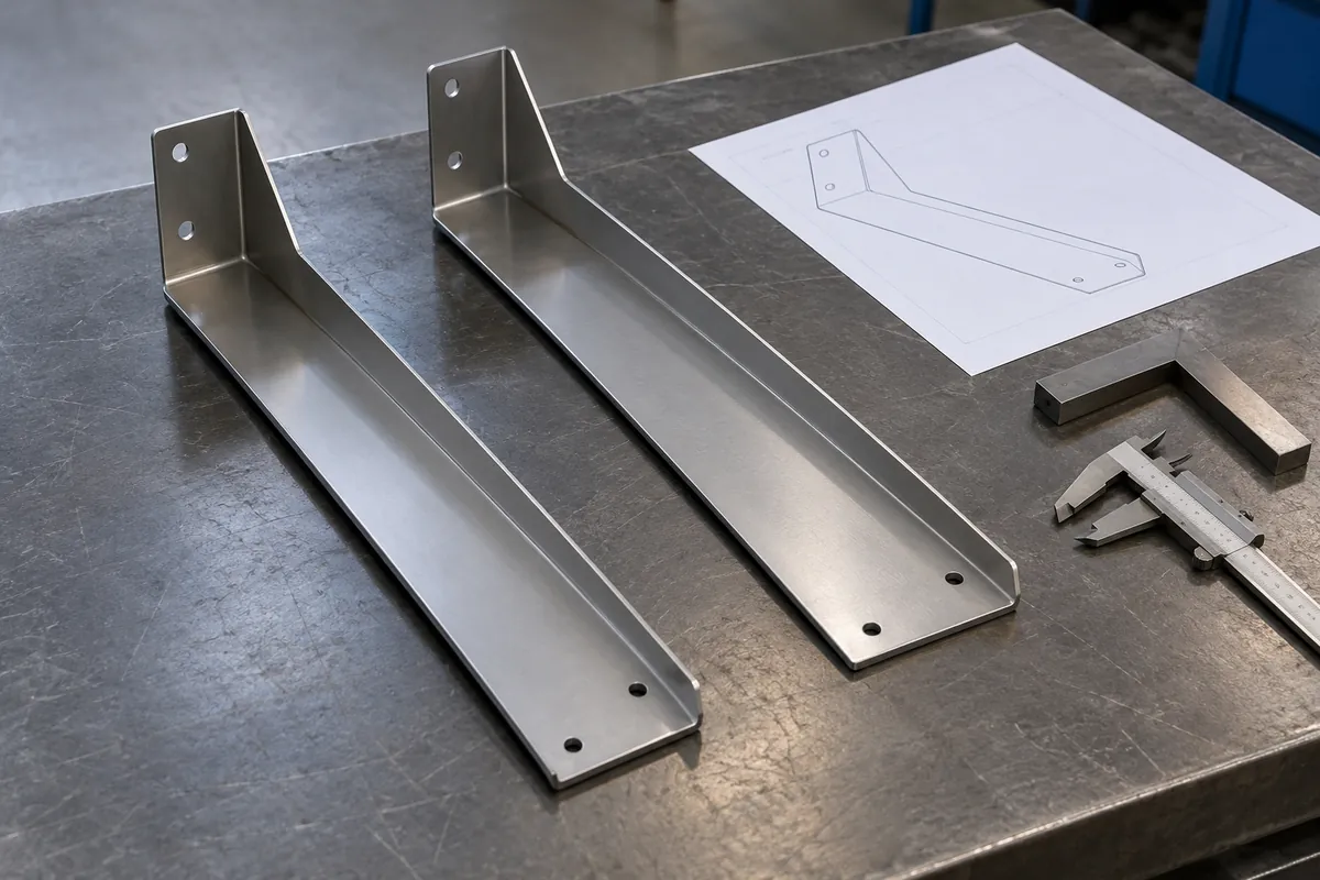
Revisit the approval when a change could alter the locating edge, contact surface, clearance or formed geometry. Examples include a revised blank outline, different flange length, altered bend sequence, new material or thickness, changed finger geometry, tool maintenance, a new contact pad, or a different assembly interface.
The trigger should be based on the specific drawing and process risk. A minor administrative update may not affect locating; a small geometry change near a finger contact may. Ask the supplier to explain the effect and document whether prior evidence remains representative. If the supplier cannot show that the change is outside the approved contact and datum system, a focused repeat sample may be appropriate.
Change control is especially important for long parts because a small shift in contact can produce a visible difference at the far end. Do not assume that a setup approved on a shorter variant automatically covers the longest or most asymmetric part. The supplier should state which dimensions, bend operations and part family members the sample represents.
For recurring orders, connect the approved finger arrangement to a controlled drawing or setup reference. Record the component revision, critical datum, setup identifier if available, inspection method and acceptance outcome. The goal is not to demand undisclosed proprietary tool design; it is to preserve enough information for the buyer and supplier to know whether a later sample follows the approved locating logic.
What should a buyer ask an OEM supplier?
A useful conversation is specific, neutral and tied to the part. Ask the supplier to walk through the drawing’s functional datum, the edge or feature used for backgauge contact, and how the long part is prevented from rocking at the relevant bend. Ask which bend sequence is assumed, where clearance is tight, and what evidence will confirm that the flange is aligned after forming.
Koitor’s approved scope includes sheet-metal forming and bending discussion, drawing and sample development, and OEM hardware coordination. The exact equipment, tooling, backgauge configuration and accepted dimension must be confirmed for each project. No particular machine accuracy or in-house measurement capability is implied here. Share the controlled drawing or physical sample, identify the assembly function, and make the buyer’s acceptance question explicit.
For broader OEM product-development context, see the OEM home storage hardware manufacturer page. A sourcing team can send its drawing, sample photographs and datum question through اتصل بـ «كويتور». The most useful request is not “make it straight”; it is “show which datum controls this flange, how the blank contacts the stop, and what representative evidence demonstrates the approved relationship.”
Practical takeaway
For press brake backgauge fingers datum flange skew, define the functional datum first, then confirm which backgauge contacts locate the blank for each relevant bend. Review seating, flange relationship and assembly fit on a representative sample; keep angle, cosmetic marks and flatness as separate checks. Treat supplier settings and finger configurations as project-specific, and record the changes that require renewed approval.
الأسئلة الشائعة
Do long parts always need two backgauge fingers?
No universal rule applies. The contact arrangement depends on part length, edge condition, flange geometry, tooling access and bend sequence. Ask the supplier to demonstrate the intended locating logic on the actual part.
Can a photo prove that a flange is not skewed?
A photo can show contact and support context, but it cannot replace a defined dimensional or assembly check. Use the inspection method and datum specified for the product.
Is flange skew the same as bend-angle variation?
No. Skew concerns the flange’s relationship or alignment along the defined datum; angle variation concerns the included angle. The issues can coexist, but they require distinct checks.
What if the fingers contact a different edge after a design revision?
Recheck whether the new edge is controlled and functionally suitable. Update the datum and setup record, then decide with the design owner whether a representative sample must be reapproved.
Should a buyer specify the backgauge machine brand or axis count?
Only if the project has a justified requirement. Usually the buyer should specify the part datum, contact relationship and evidence needed; the supplier can propose suitable equipment and tooling.
What evidence belongs in a repeat-order record?
Keep the drawing and material revision, bend sequence, contact points, sample identity, inspection method, assembly result and any approved changes. State the limits of what the sample represents.
Technical reference:
- ADH Machine Tool: Press Brake Stop Fingers and Contact Geometry
- ADH Machine Tool: Backgauge Finger Design and Press Brake Accuracy
Review a formed hardware datum question
Share the controlled drawing or sample, the functional datum and the flange relationship that needs approval for your OEM project.
OEM / العلامة التجارية الخاصة
حوّل دليل التوريد هذا إلى موجز منتج
يرجى إطلاعنا على المنتج المستهدف، والحجم، والتشطيب، وكمية الطلب، ومتطلبات التغليف. وسيتلقى فريقك تقييمًا عمليًّا لإمكانية التصنيع قبل تقديم عرض الأسعار.
 English
  Español
  Português
  Français
  Deutsch
  العربية