
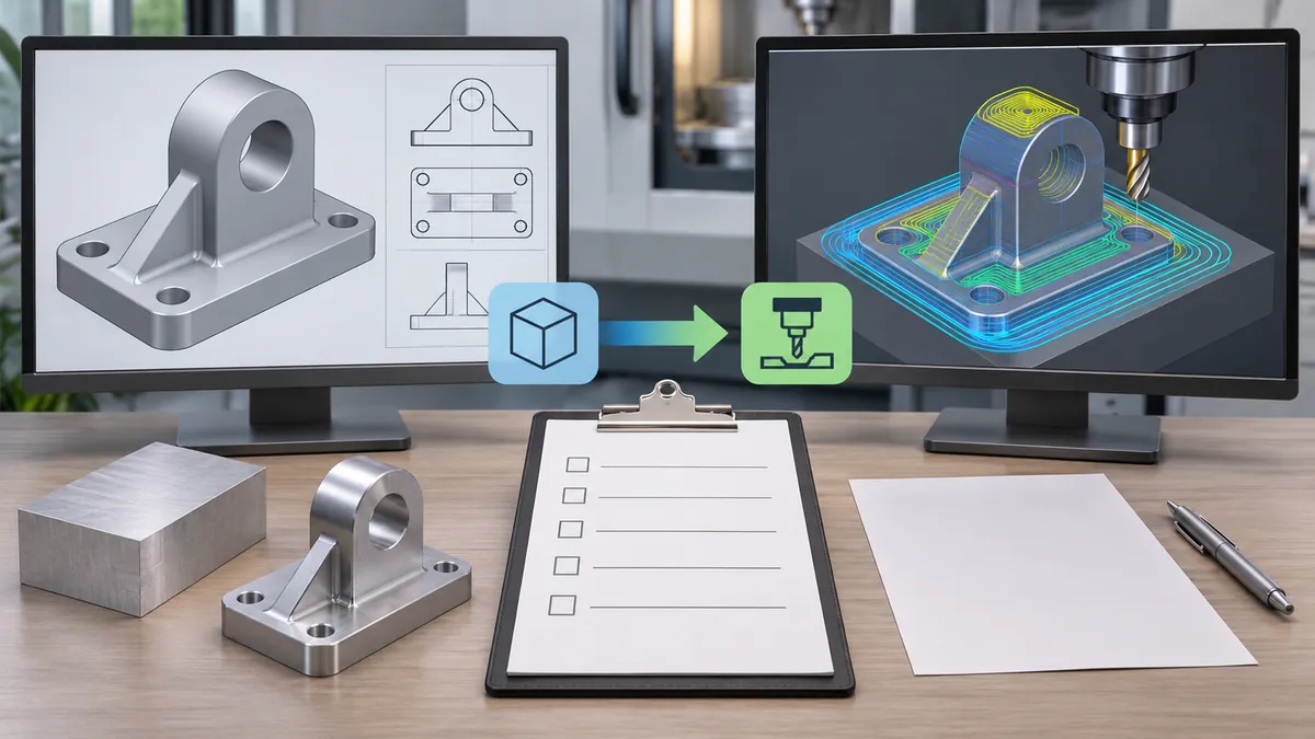
CAD vs CAM describes two related but distinct roles. CAD, or computer-aided design and drafting, helps define a product’s geometry and design information. CAM, or computer-aided manufacturing, helps prepare manufacturing operations and generate instructions for a particular process and equipment. A CAD model is not automatically a machine-ready program. Even when one software suite includes both functions, manufacturing output still depends on the actual part, machine, tooling, setup, postprocessor and approval controls.
What CAD does in a product workflow
CAD tools are used to create, modify and communicate digital product geometry. Depending on the software and project, the design may include 2D drawings, 3D parts, assemblies, dimensions, annotations, materials or other product data. The intended deliverable might be a concept model for discussion, a controlled drawing for quotation or production, or a native design file used by the engineering team. Buyers should identify which one they are sending because those artifacts serve different purposes.
A CAD model can show shape and relationships, but it may not define every manufacturing requirement. Material grade, temper, finish, critical tolerances, cosmetic faces, weld notes, inspection criteria, packaging and approved substitutions may be absent or incomplete. A three-dimensional representation can look precise while still leaving the supplier unsure which dimension is controlled or what acceptance result the buyer expects. The design owner must put those requirements in the appropriate drawing, specification or project record.
CAD also does not necessarily mean that the model is fully parametric or that every feature can be edited as the original designer intended. A neutral model may provide geometry without the source feature history. A screenshot may communicate appearance but not dimensions. A rendered image may show a concept but omit manufacturing details. State the file status and permitted use, especially when the model is preliminary or supplied for quotation only.
Where a BOM is included, confirm that its part numbers and quantities match the model instances and the quotation. A missing component can change assembly labor or packaging even if the core bracket geometry is unchanged. If the model intentionally suppresses a purchased part for file-size or confidentiality reasons, state that fact and identify whether the supplier should include it, source it or leave it outside the order. That commercial boundary belongs in the product definition or purchase scope, not as an assumption inside the CAM plan.
What CAM does in a manufacturing workflow
CAM is used to plan and prepare manufacturing operations from design information. Depending on the process and software, that work may include selecting an operation, defining tool or process paths, setting operation parameters, organizing steps and producing output for a particular machine or controller. The resulting file is not a generic consequence of geometry; it is tied to the intended manufacturing route and the system that will execute it.
CAM output can depend on the machine, controller, tooling, workholding, material, process configuration, postprocessor and operator setup. A toolpath that appears plausible in a planning environment is not automatically safe or suitable for every machine. The responsible manufacturing team needs to validate the output in the context of its equipment and procedures. This article does not provide programming directions or claim that a model can be converted into a reliable production program without review.
A buyer usually purchases a finished part, assembly or manufacturing service rather than a CAM file. The supplier may create and control its own process plan. If the buyer needs visibility into a particular setup, inspection stage or approval, that should be stated as a project requirement. A supplier’s CAM workflow does not replace the buyer’s product specification, and a buyer’s CAD model does not dictate every internal operation unless the contract requires that control.
| Workflow stage | Typical information or output | What it does not automatically establish | Buyer or supplier responsibility to clarify |
|---|---|---|---|
| Product definition in CAD | Part geometry, dimensions, assembly relationships and annotations | Complete process route or machine-ready output | Which drawing/model revision controls and what requirements are missing |
| Design review | Feasibility questions, changes and approval record | That a part has been made or inspected | Who approves material, geometry and specification changes |
| CAM preparation | Process plan, operations, paths or machine-specific output | Safe execution on every machine or verified finished-part quality | Which supplier validates the selected route and output |
| Machine setup and execution | Equipment-specific setup and operation | Compliance with unspecified tolerances or finish criteria | How the supplier controls the job and verifies the result |
| Inspection and acceptance | Evidence against stated requirements | Properties not measured or included in acceptance | Which features, method, sampling and records apply |
The matrix distinguishes product definition from manufacturing preparation. It is a responsibility map, not a universal software feature list. A specific platform may combine functions, but the work outputs and approval questions remain separate.

Where CAD and CAM connect—and where they do not
CAD supplies product information that can inform manufacturing preparation. CAM uses some of that data to plan operations. In an integrated workflow, design and manufacturing teams may review the same model or exchange changes through connected applications. Integration can reduce manual transfer, but it does not eliminate the need to confirm that the correct revision, material, equipment and process assumptions are being used.
A design change can affect manufacturing preparation. Moving a hole, changing a bend, altering thickness or revising a surface can require a new process review. The supplier should determine whether the current setup, toolpath or operation plan remains valid. The buyer should communicate the change through controlled documents and obtain confirmation that the supplier has replaced the prior version. Do not assume a software link has automatically updated all downstream files or shop-floor records.
The transition also has an information boundary. A design model may not state the stock form, datum strategy, fixture, sequence, tool choice or inspection method. The supplier generally needs to plan those details for the actual production system. If a buyer has a required process, material, special characteristic or quality control, state it explicitly. Otherwise, an unclear model can force the supplier to guess whether the buyer is controlling the method or only the finished result.
The terms are not mutually exclusive software categories. One application may provide CAD and CAM capabilities; another may focus on design, simulation or manufacturing planning. Product teams should ask what role a tool performs in the workflow rather than assume the brand or license name describes every output. The important distinction for sourcing is whether the recipient has a controlled product definition and whether the manufacturing organization has validated its own execution plan.
An integrated environment can create a useful link between design data and manufacturing preparation, but the buyer should still ask how revisions are released. Does a model update automatically invalidate the prior plan? Who checks that a toolpath references the approved version? How does the supplier prevent a superseded file from reaching production? These are process-control questions, not features that can be assumed from a software label. A project can use one integrated suite and still need a formal approval point when a critical dimension or material changes.
Likewise, a CAM plan may be optimized for a supplier’s machine and schedule. That plan belongs to the manufacturing organization unless the contract explicitly transfers or shares it. The buyer should focus on the required output, acceptance evidence and change controls. Requesting an internal program without knowing how to review it may expose proprietary process details without improving product quality. A more useful request may be a feasibility confirmation, sample, inspection report or approval record tied to the product requirement. This boundary is central to CAD vs CAM: product ownership and process preparation can inform each other without becoming the same deliverable.
What a buyer should send for a manufacturing handoff
Identify the product definition
Send the approved model or drawing and state the part number, revision and status. If the model is a concept, label it as such. If the drawing controls dimensions while the model controls shape, say so. If the two conflict, identify which document governs and ask the recipient to flag the mismatch before quoting or making the part.
Include requirements CAD may not contain
Provide material and finish, critical dimensions, cosmetic faces, joining notes, load or fit requirements where applicable, inspection criteria and packaging expectations. Do not assume the supplier can infer these from a shaded model. If a requirement is still open, mark it as open and ask for a proposal rather than presenting an incomplete drawing as a final specification.
Define who owns process decisions
State whether the supplier may choose the manufacturing route or must follow an approved process. If a process change requires approval, specify the review trigger. For a finished component, the buyer may care primarily about conformance to the drawing; for a controlled or validated product, the process itself may also be contractually constrained. The supplier should identify assumptions and ask before making a change that affects agreed requirements.
Confirm the supplier’s acceptance of the handoff
Ask the recipient to confirm the model and drawing revision it received, any missing information, and whether it can review the requested geometry. This is not a request for proprietary machine code. It is a simple check that buyer and supplier are working from the same product definition. If the supplier needs a different file format, arrange that transfer and verify the result according to the actual software workflow.
Establish the change and approval path
Agree how a drawing or model change reaches the supplier and who approves it. A revision should identify whether the change affects geometry, material, finish, tolerance or only documentation. The supplier can then assess whether its current planning remains applicable. The buyer should ask for acknowledgement that the latest controlled file has replaced earlier copies, especially when a quote, sample or production order is already underway.
For a first article or sample, identify the purpose of the review. It could confirm fit, appearance, dimensions, assembly sequence or another stated feature. Do not imply that approval of the sample also approves the supplier’s hidden production plan unless the contract says so. If a process-specific approval is required, define which evidence will be provided and how the approval is recorded. This avoids leaving the supplier to infer how much of its CAM work the buyer expects to review.
The buyer can use a compact change log to connect the design decision to the supplier’s response. Record the prior revision, new revision, affected feature, reason for change, approval owner and date the supplier acknowledged receipt. If the change is editorial and does not affect product definition, note that as well. This makes it easier to distinguish a corrected drawing annotation from a geometry change that may require new planning or a new sample.
For a geometry revision, ask the supplier to identify affected manufacturing steps and whether any existing material, tooling or work in process is involved. This is a coordination question, not a demand for disclosure of proprietary toolpaths. The buyer needs to understand schedule, cost and conformity consequences that affect the order. The supplier can summarize those impacts at a suitable level while retaining responsibility for its machine-specific program and production controls.
If a change occurs after a sample has been approved, determine whether the approval still applies. A moved hole, altered bend or new finish requirement can invalidate evidence gathered on the earlier part. A minor title-block correction might not. The responsible technical owner should make that decision using the changed feature and acceptance criteria. Record whether a new sample, drawing review or measurement report is required before production resumes.
This discipline is useful even when a small supplier communicates informally. A clear email thread can accompany the controlled revision, but it should identify the exact file and decision. Avoid phrases such as “use the newest model” when several files or quote versions exist. Ask the recipient to confirm the part number and revision it will use, and keep the approval with the order record so a future reorder can follow the same basis.
The information handoff should distinguish required facts from optional context. A 3D model can help a supplier understand shape, while a drawing carries controlled dimensions; a note may explain a critical cosmetic face; a BOM may define component scope. A buyer should avoid sending several contradictory files without identifying authority. If files conflict, the supplier should raise the conflict and the product owner should resolve it before manufacture rather than allowing the CAM programmer to select a preferred interpretation.
A practical CAD-to-CAM responsibility sequence
- Define the product. The buyer or product owner controls the required geometry, material, finish and acceptance criteria.
- Issue the controlled data. Identify part number, revision, file status and the document that governs.
- Review manufacturability. The supplier identifies unclear features, process constraints and assumptions for the actual route.
- Approve design changes. The product owner decides whether a proposed geometry or material change is accepted.
- Prepare manufacturing operations. The supplier creates process-specific planning and output for its equipment.
- Validate the execution plan. The responsible manufacturing team checks the plan against machine, tooling, setup and process controls.
- Make and inspect the part. The supplier verifies the defined features and records results as agreed.
- Close the feedback loop. Any nonconformance or approved change is linked to the current revision and future orders.
This sequence clarifies responsibility without requiring a buyer to dictate the supplier’s internal CAM operations. A buyer can ask for a feasibility review and confirmation of the resulting part while allowing the supplier to select a suitable process, where the contract permits. If the buyer needs process records or approval of an operation, it must define that expectation before production.
Hypothetical hardware example
Imagine an importer sends a CAD model of a bent metal mounting bracket with two holes and a small locating tab. The file shows shape and nominal dimensions, but it does not identify the alloy, thickness, bend requirement, cosmetic face or critical fit tolerance. The supplier can understand the general concept but cannot reliably infer those omitted requirements from the model alone.
The importer adds a controlled drawing that identifies the material and finish, calls out the hole spacing and tab fit, and marks the visible face. The supplier reviews the geometry, proposes an operation sequence and prepares its own manufacturing plan. If the supplier recommends moving a hole to improve fabrication, it submits the revision for buyer approval. After approval, it prepares and validates machine-specific output, then produces a sample for the agreed dimensional and visual checks.
The buyer’s CAD model defines the product intent; the supplier’s CAM planning addresses how its equipment will manufacture the part. Neither file replaces the other’s responsibility. The buyer should not ask for a machine program unless it has a defined reason and authority to receive it. The supplier should not treat an unapproved process plan as permission to change the product definition.
This example is hypothetical. It is not a Koitor production case, customer result, software capability statement or claim of automatic design-to-machine conversion. It illustrates a typical responsibility boundary for discussion.
Common handoff mistakes
- Treating a CAD model as a complete production specification. Check material, finish, tolerance and acceptance separately.
- Assuming CAD and CAM are always separate applications. A tool may integrate both roles, but outputs still need validation.
- Assuming CAM output is machine independent. It depends on equipment, controller, tooling, setup and postprocessor.
- Expecting a neutral model to preserve every design feature. Clarify whether geometry or native history is required.
- Letting the supplier guess at missing requirements. Mark open items and ask for a controlled clarification.
- Changing a drawing without replacing downstream files. Confirm the supplier’s current revision and process plan.
- Requesting machine code without a business need. Define what information the buyer actually needs to approve.
- Treating a screenshot as a model. Send controlled geometry and a drawing for dimensions.
- Assuming software integration guarantees quality. Inspect the finished part against the defined acceptance criteria.
- Leaving process-change authority unclear. State which substitutions require prior approval.
Frequently asked questions
What is the main difference between CAD and CAM?
CAD is used to define or modify product geometry and related design information. CAM is used to prepare manufacturing operations and generate process-specific output. A single software suite may include both functions.
Does CAD automatically create a machine-ready program?
No. Manufacturing output depends on the selected process, equipment, tooling, setup and postprocessor, and it requires validation by the responsible manufacturing team.
Is a 3D CAD model enough to quote a custom metal part?
It may communicate shape, but it may omit material, finish, tolerances, critical features, inspection or packaging. Provide a controlled drawing or written requirements where those details matter.
Does CAM change the product design?
CAM prepares manufacturing operations. A supplier may identify design changes that could improve feasibility, but the product owner should approve changes to controlled geometry or requirements.
Should a buyer request the CAM file?
Only when there is a defined project or contractual need. A buyer purchasing a finished part usually needs confirmation of the product requirements and acceptance rather than the supplier’s machine-specific program.
Can a CAD file preserve the native feature history?
Do not assume so. Neutral exchange may transmit geometry without the original parametric design tree. Clarify whether editable native history is required or whether a neutral model and drawing are sufficient.
What should be confirmed before manufacturing begins?
Confirm the part number and revision, governing drawing, material, finish, critical features, acceptance criteria, process-change authority and any outstanding supplier questions.
How can Koitor help with the design-to-manufacturing handoff?
Koitor Hardware is a family-owned custom metal hardware factory with approved drawing and sample communication. Buyers can share controlled product information and discuss project requirements. This does not claim ownership of particular CAD/CAM software or automated toolpath services.
Sources and scope
Scope note: This guide distinguishes product definition from manufacturing preparation. It does not provide CAM programming instructions, promise seamless software transfer or establish Koitor software or machine capabilities.
Review product data before a custom hardware quote
Share the controlled drawing or model, revision, material, finish and critical acceptance requirements. Koitor can discuss the custom hardware project within its confirmed scope.
OEM / PRIVATE LABEL
Turn this sourcing guide into a product brief
Share your target product, size, finish, order quantity and packaging requirements. Your team receives a practical manufacturability review before quotation.


 English
 Español
 Português
 Français
 Deutsch
 العربية