

Progressive die pilot pin strip feed pitch misfeed problems are often caused by a mismatch between the strip’s actual feed position and the die’s intended registration point. Buyers sourcing stamped hardware should ask how the strip is indexed, how feed release and pilot engagement are coordinated, and what evidence confirms that hole locations and formed features stay aligned across the production run. The exact setup depends on the die, feeder and part design.
What Problem Does This Article Help Buyers Solve?
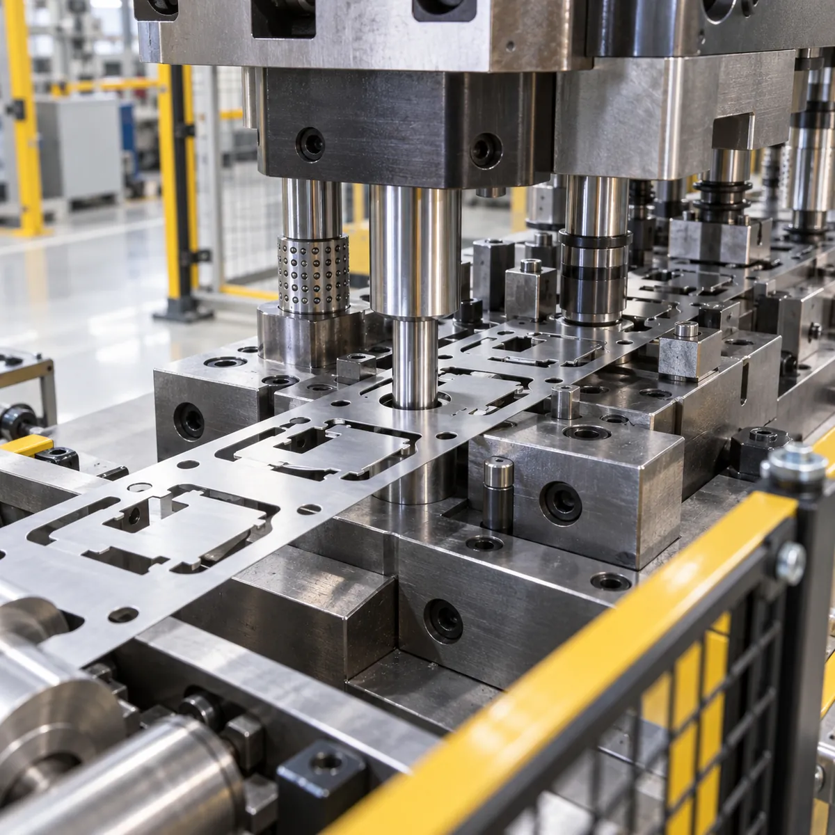
A progressive die performs multiple operations as a metal strip advances through stations. If the strip advances too far, too little, or is not released at the right time, a pilot pin may fail to enter its registration hole correctly. Misfeeds can cause feature position errors, deformation, tool damage or a stop in production. A finished component may still appear acceptable at a glance even when a critical hole or formed tab is misplaced.
This is relevant to buyers of stamped brackets, mounting plates and small hardware components. It is a process-control topic, not a claim that Koitor operates a progressive die or feeder. The buyer’s role is to define critical dimensions and ask the stamping supplier how feed alignment is controlled and monitored.
What Should Importers Check First?
Review the strip layout and the part drawing together. Identify feed pitch, pilot-hole position, station sequence, carrier width, material thickness and the critical features that depend on registration. Ask which holes are used for piloting and how they relate to the final part datums. A hole created in an earlier station can be a reference for later operations, but only if its geometry and strip condition remain suitable.
Ask the supplier how its feeder releases or relaxes the strip while the pilot enters, and how the die and feeder timing are set and verified. A feeder setup guide from a machinery supplier discusses release timing as a factor in accurate feeding; the actual values and sequence must come from the selected press, feeder and tool documentation. See this roller-feeder timing reference.
How Do Materials, Structure, and Tooling Affect the Result?
Strip behavior depends on material, width, thickness, flatness, coil set, burr direction and the support provided by the die. A feed system that works on one stock condition may not behave identically after a material or thickness change. The pilot pin’s lead-in and the hole size also affect engagement, while excessive clearance can permit movement and insufficient clearance can cause interference or damage.
Tooling setup involves more than entering a nominal feed length. The die designer and press operator consider station spacing, strip advancement, pilot entry, stock lift, feed release, press timing and safe operating conditions. Buyers should not prescribe machine adjustments remotely; they should request that the stamping supplier document the control plan and show that the critical part features remain within drawing requirements.
| Buyer Requirement | What to Check | Why It Matters |
|---|---|---|
| Strip layout | Pitch, pilot-hole location, carrier and station sequence | Ties tool registration to final part features |
| Stock condition | Material, thickness, width, flatness and burr orientation | Changes feeding and pilot engagement behavior |
| Timing | Feeder release and pilot entry sequence | Prevents strip tension or restraint during registration |
| Detection | Misfeed detection, press stop and operator checks | Limits damage and nonconforming output |
| Part evidence | Critical dimensions and sample records | Confirms the final component, not just machine settings |
How Should Buyers Compare Feeding and Registration Approaches?
The die and feed system should be designed as a coordinated process. Pilot pins can establish local strip registration at the tool, while the feeder advances stock by a target pitch. Some layouts use additional guides or sensors to support alignment and misfeed detection. The best arrangement depends on strip stiffness, part geometry, tolerance needs, press configuration and cycle conditions.
| Control point | What it helps control | Buyer evidence |
|---|---|---|
| Feeder pitch | Amount of strip advancement | Setup record or approved strip sample |
| Pilot pin and hole | Local registration at the die station | Tool layout, pin/hole geometry and first-piece check |
| Feed release timing | Strip freedom during pilot engagement | Supplier’s setup procedure and verification record |
| Misfeed sensor/stop | Abnormal strip movement or missing material condition | Functional check and reaction plan |
What Are Common Mistakes When Sourcing This Product?
Do not specify only the final part dimensions and assume strip feeding is automatically stable. Ask which dimensions are sensitive to pitch or station registration. Another common mistake is changing stock thickness, coil source or lubricating condition without reviewing the feeder and pilot setup.
Avoid treating a feeder’s displayed pitch as proof that each station registers correctly. A number on a control screen does not verify pilot entry or final part geometry. Confirm first pieces after setup or changeover and define how the supplier checks the critical features during production. If a misfeed occurs, ask how potentially affected parts and tool conditions are contained before production resumes.
How Can a Small-Batch OEM Factory Help?
A metal hardware factory can help the buyer understand which stamped features affect assembly and what sample dimensions should be highlighted in the drawing review. Koitor’s relevant role is custom metal hardware manufacturing and buyer communication; this article does not claim a specific press, progressive die, feeder or pilot-pin capability.
For an OEM project, mark critical holes, slots, bends and mounting interfaces before quotation. Ask the supplier to identify whether the proposed stamping route uses progressive tooling or another method and what changes require a new setup review. Discuss production volume, tooling ownership, sample approval and change control separately; do not infer a supplier’s equipment from a product photograph.
Buyers can review Koitor’s OEM hardware manufacturing information and send a drawing or sourcing question through the contact page.
Distinguish Feed Error from Tool and Part Error
A misfeed report should describe what moved, when it moved and which feature was affected. Strip feed pitch, pilot engagement, stock straightening, coil set, feed release timing, pilot clearance and press motion can interact. A hole that appears off-location on a finished part may come from registration, but it can also result from a worn tool, material variation, a burr, strip distortion or an incorrect part datum. Buyers should avoid assigning “pilot pin error” from a single dimensional result without reviewing the strip and process evidence.
Ask the manufacturer to show how the strip is located at the critical station and how the pilot enters the stock relative to the feed release. The relevant question is not merely whether a pilot pin exists; it is whether the strip has relaxed enough to register without being dragged or buckled. The appropriate sequence depends on the die design, feed equipment, stock thickness and press timing. A process note should therefore describe the actual setup, not prescribe a universal timing value.
When evaluating stamped mounting plates, identify the datum features and the dimensions that matter downstream. A hole-to-edge measurement may be adequate for a simple bracket, while a multi-hole pattern may require positional relationships referenced to a functional datum. If the part is formed after piercing, state whether inspection occurs before or after forming and how the part is held. Otherwise, a buyer may compare measurements taken under different conditions and mistake the difference for a feeding problem.
Sample Evidence and Change Control
During first-article review, request a sample set that represents the intended production material and thickness. Check critical hole locations, pitch-related features, burr direction, edge condition and any form features that could shift the datum. Ask whether the report reflects parts from a stable run or only setup pieces. Early setup parts can reveal tooling direction, but they are not necessarily representative of the steady-state process after the feed and die are adjusted.
For recurring production, ask the supplier how misfeeds are detected and what happens after a stop or restart. The relevant controls may include sensor checks, feed-length monitoring, operator response, strip-end handling and restart inspection. Do not assume any one control is present; have the supplier explain the actual equipment and work instruction. Agree whether samples after a jam, coil splice, die adjustment or maintenance event need additional verification before the line returns to normal production.
Keep a controlled record of the approved strip layout, die revision, feed setup and inspection method where those details affect the part. If the material width, thickness, temper or supplier changes, assess whether the pilot and feed setup need requalification. Similarly, a die repair or replacement pilot can affect registration. A change-control trigger should be based on potential effect on the drawing characteristics, not on paperwork convenience.
When a defect occurs, preserve the strip or affected pieces if possible. Compare the blank layout and feature locations against a known-good sample, then inspect whether the error repeats at a constant pitch or varies across stations. A constant shift may point toward a datum or setup issue; progressive drift or irregular marks can suggest another cause, but these are diagnostic clues rather than proof. A focused supplier review should combine the part measurements, die layout and event history before corrective action is approved.
Supplier Questions for a Repeatable Stamping Process
Ask the supplier to explain which part characteristics are most sensitive to strip registration and how they are monitored during the run. The answer should connect the die layout, feed equipment and inspection plan to the drawing. If the supplier monitors feed length or uses a detection device, ask what event causes a stop and how production restarts after an alarm. These are questions for the actual process owner; do not presume that a particular sensor, feeder function or control is installed.
Clarify how stock is identified and protected between receipt and the press. Coil width, thickness, flatness, surface condition and material traceability can influence feeding and part dimensions. If a new material lot behaves differently, the process owner should be able to compare the lot information with the approved sample and assess whether setup changes are necessary. Buyers should avoid making process adjustments based only on a single defect without confirming the stock and die conditions.
For a sourcing audit, review a representative control plan, first-article record, nonconformance example and maintenance/change record. The goal is to see whether the supplier can explain how a problem is detected, contained, corrected and verified—not to demand confidential tooling details unrelated to the purchased feature. Agree which evidence is shared with the buyer and how revisions are communicated.
Use progressive die pilot pin strip feed pitch misfeed as the issue label when requesting a corrective-action review, then describe the actual symptom and affected dimension. The label helps route the question; it is not a conclusion that the pilot pin caused the defect. The supplier’s response should identify the evidence checked and the reason for the selected correction, with a follow-up sample or measurement to confirm the change worked.
In short, progressive die pilot pin strip feed pitch misfeed is a symptom category to investigate, not a confirmed root cause until the strip, die and part evidence agree.
Buyer Checklist Before Requesting a Quotation
- Share the part print and, where available, a strip layout.
- Identify critical features tied to feed pitch or pilot registration.
- State stock grade, thickness, width and surface condition.
- Ask how pilot pins, feeder pitch and release timing are coordinated.
- Confirm the first-piece and in-process checks for key dimensions.
- Ask how misfeeds are detected and affected parts contained.
- Define the revalidation needed after material, tool or feeder changes.
Häufig gestellte Fragen
What does a pilot pin do in a progressive die?
A pilot can help register the strip locally at a station by entering a suitable hole. The exact design and control strategy depend on the tool and work material.
Is feed pitch the same as pilot accuracy?
No. Feed pitch is the intended strip advancement, while pilot registration and tool condition determine local alignment at the station. Both should be reviewed.
What causes a pilot pin to miss its hole?
Potential causes include feed-position error, timing mismatch, strip distortion, incorrect hole geometry or setup problems. A tooling specialist should diagnose the actual event.
Does Koitor use progressive dies for every stamped component?
No such universal equipment claim is made. Buyers should confirm the manufacturing route for each product and supplier.

Arbeiten Sie mit Koitor Hardware zusammen
Sourcing a Stamped Hardware Component?
Share the part drawing, critical feature list, material condition and target order quantity. Koitor can discuss OEM manufacturing fit and sample checkpoints; the exact stamping route and equipment must be confirmed for the project.
OEM / EIGENE MARKE
Verwandeln Sie diesen Beschaffungsleitfaden in ein Produktdossier
Teilen Sie uns Ihr Zielprodukt, die Größe, die Oberflächenausführung, die Bestellmenge und Ihre Verpackungsanforderungen mit. Ihr Team erhält vor der Angebotserstellung eine praxisorientierte Prüfung der Herstellbarkeit.


 English
 Español
 Português
 Français
 Deutsch
 العربية