
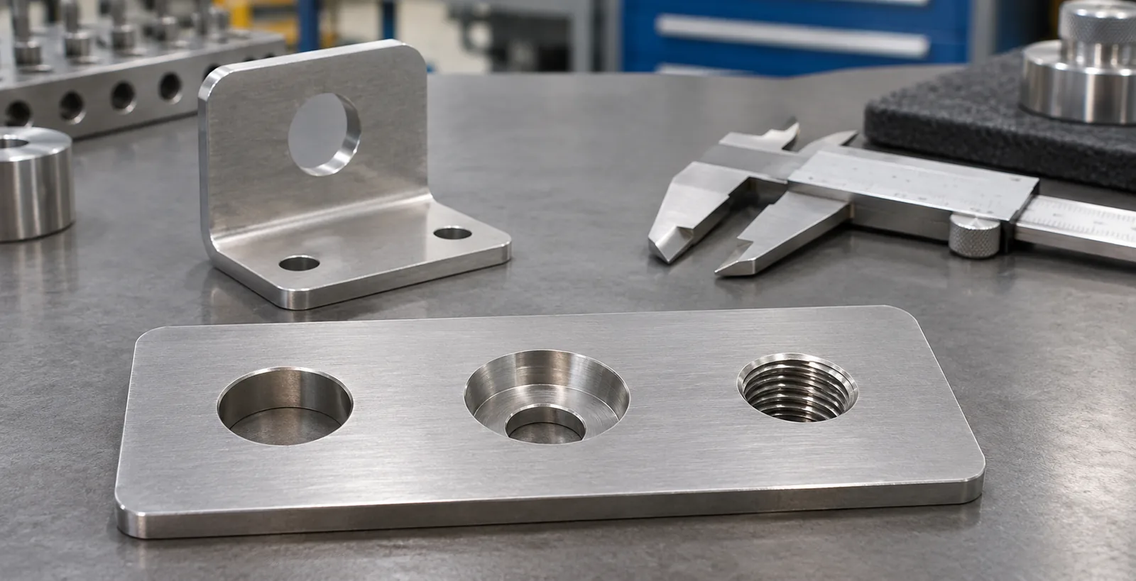
Hole types are best understood as several independent descriptions of one feature: whether it passes through the material, what shape any recess has, whether its wall is threaded, and what mating purpose the opening serves. A single opening can therefore be a blind, tapped hole with a counterbore, or a through clearance hole with a countersink; these are not necessarily competing labels. For a hardware buyer, the practical task is to identify each applicable feature and state the dimensions, location, and finished condition that matter to assembly. A name alone does not specify a complete drawing requirement or prove a supplier’s manufacturing capability.
What do hole types describe on a hardware drawing?
The phrase “hole types” is a broad family label, not a single mutually exclusive classification. A drawing may describe one opening by depth, entry shape, internal thread, fit purpose, cross-section, position, or the operation used to create it. Those descriptions answer different questions. Confusing them can leave a supplier to infer whether a fastener must pass through, sit flush, engage threads, or stop at a particular depth.
A useful way to read the feature is to ask four questions independently:
- How far does the opening extend? It may pass through the specified wall or stop inside it.
- What shape is at the entry or seat? The opening may have a cylindrical recess, a conical recess, a shallow flat seat, or no special recess.
- What is the wall intended to do? It may be plain, threaded, or intended to provide clearance for a separate fastener.
- Where is the feature and what must it mate with? Location, orientation, component relationship, and the actual screw, insert, pin, or other part determine whether the feature is useful.
These questions form a map rather than a universal taxonomy. Not every part needs every descriptor. A simple wire support may have a plain opening in a tab, while a mounting plate may combine a clearance opening, a countersink, and a defined position. A purchased insert can have its own thread while the receiving sheet-metal opening remains an unthreaded hole. The terms should describe the specific feature in the specific component.
| Description axis | Question answered | Examples of useful wording | What the name alone does not establish |
|---|---|---|---|
| Extent | Does the opening pass through the stated thickness? | Through; blind; depth stated from a named face | Diameter, location, or remaining wall thickness |
| Recess geometry | Is material enlarged or shaped at the entry? | Counterbore; countersink; spotface when applicable | The mating fastener, exact size, or acceptable seating condition |
| Wall condition | Does the wall contain an internal helix or stay plain? | Tapped/threaded; plain; clearance | Thread series, fit, depth, or fastener compatibility |
| Function | How is the feature expected to interact with another part? | Clearance for a specified fastener; locating; passage | Whether the geometry will work without the mating-part information |
| Position and orientation | Where is the feature relative to the part? | Coordinates or dimensions from stated datums | Tolerance, datum scheme, or inspection method unless given |
| Production route | How might the feature be made? | Drilled, punched, formed, machined, or made with an insert | A guaranteed method or capability of a particular supplier |
The table is a communication aid, not a substitute for a controlled engineering drawing. Terms and symbols can depend on the drawing system, supplier, component, and applicable specification. If a project relies on a particular standard or fastener family, identify it explicitly and confirm the interpretation with the responsible engineering contact. Do not assume a generic web diagram overrides the project drawing.
Why are through and blind openings different descriptions?
“Through” describes an opening that continues through the specified material thickness. “Blind” describes an opening that stops within the material rather than emerging on the opposite face. The distinction concerns extent; it does not tell the reader whether the opening is threaded, recessed, or intended for clearance. Autodesk’s hole-feature documentation lists placement, extent, hole type, tap type, drill point, depth, diameter, and thread settings separately. Protolabs’ CNC hole-design guide likewise defines through and blind by whether the opening passes through the part. These examples support keeping the concepts distinct; neither interface nor provider guide is a mandatory drawing standard.
For a buyer, the most important question is which depth is functionally needed. With a blind drilled opening, the straight-sided portion available for a pin or screw may differ from the total tool depth because a drill point or other bottom geometry can occupy additional space. A threaded blind feature also raises a separate question: how much usable thread engagement is required, and what is the bottom clearance? A generic depth number can be ambiguous if the drawing does not explain what surface and what portion of the hole it measures.
The phrase “blind hole” alone does not establish a safe remaining wall, adequate engagement, or a universal depth-to-diameter ratio. Those decisions depend on the part material, thickness, load path, fastening arrangement, manufacturing route, and applicable design requirements. A buyer should not copy a rule of thumb from a different component and treat it as a verified specification for a bathroom shelf bracket or a storage-rack plate.
Before approving a blind feature, clarify:
- The face from which depth is measured.
- Whether the stated depth means total depth or usable straight-sided depth.
- Whether the bottom form matters to assembly or inspection.
- Whether a thread is required and, if so, the usable engagement requirement.
- The remaining material condition that engineering has approved.
- Whether the opposite surface is cosmetic, functional, or exposed to moisture.
For a through feature, confirm which wall or stack of components it passes through. “Through” can be misunderstood when a drawing contains several layers, a folded return, a tube wall, or a separate insert. State the component and face, and show the feature in a view or section that removes ambiguity. If the opening must clear a fastener across a stack, the relevant condition concerns the assembled components, not only one isolated plate.
What is the difference between a hole and its entry recess?
A basic opening and a recess around its entrance are separate geometric ideas. A counterbore is a cylindrical enlargement coaxial with a smaller opening; a countersink is a conical enlargement. A spotface is generally a shallow flat seating area, but the exact project definition and drawing convention should be confirmed. These names describe entry geometry; they do not by themselves describe whether the smaller opening is blind or through, or whether it is threaded.
A counterbore can be paired with a through or blind opening. A countersink can also be paired with a through or blind opening. In both cases, the fastener and the mating surface determine why the recess is present. A cylindrical seat may be selected for a particular head or bearing arrangement; a conical seat may be selected for a compatible tapered head. A shallow flat seat may be considered when the surrounding surface is not suitable for the intended bearing contact. None of those descriptions guarantees a flush or secure assembly without the matching dimensions and fastener details.
Do not collapse a small edge break or deburring chamfer into the word “countersink.” A chamfer may remove a sharp edge or facilitate assembly without being sized to accept a countersunk fastener. If the surface is cosmetic or the fastener must sit at a controlled height, the drawing should identify the functional recess and the intended mating condition. Otherwise, a supplier could interpret a small edge treatment where the design requires a fastener seat, or machine a larger feature than the part can accommodate.
For a deeper comparison of the two principal recess geometries, see Koitor’s article on counterbore versus countersink. This article uses only their role in the wider feature map. It does not prescribe universal diameters, angles, depths, screw standards, or manufacturing tolerances. Those values must follow the selected fastener and the controlled project requirement.

How do threaded, plain, and clearance openings differ?
A threaded opening has internal helical geometry intended to engage a compatible external thread. A plain opening has no such internal thread. A clearance opening is described in relation to a separate fastener that should pass through it; its exact fit depends on the fastener, application, and project specification. These terms focus on the wall or intended relationship, not on whether the opening is through or blind.
A threaded feature may be cut directly into a sufficiently suitable component, or a separate threaded insert may provide the mating thread. Which construction is appropriate depends on material, thickness, loading, serviceability, production design, and the approved assembly. The presence of a thread on a drawing should not cause a buyer to assume that a thin sheet-metal component will simply be tapped directly. The actual construction and supplier’s proposed process should be reviewed against the requirement.
A plain opening can still have a precise function: it may provide clearance, locate a separate component, allow a pin or tube to pass, or support an assembly feature. “Plain” does not mean “unimportant” or “uncontrolled.” If the opening must align with a mating part, position, size, edge condition, and finished condition can matter even without threads.
Thread notes also need scope. Buyers should identify the required thread series or standard when known, nominal designation, hand if nonstandard, depth or engagement needs, and the component in which the thread exists. For inserted threads, specify whether the insert itself is part of the purchased assembly and how the receiving opening is controlled. A thread callout that omits the component or usable depth can be misread in a multi-part assembly.
Koitor’s existing guide to thread pitch addresses a different question: how pitch relates to a specified thread. Buyers should use the relevant owner page for that deeper detail rather than treating “threaded hole” as a complete thread specification.
Can one opening have more than one hole type?
Yes. Because the descriptors answer different questions, a single feature can carry several at once. Consider a hypothetical mounting plate for a bathroom accessory. Its opening could pass through the plate, provide clearance for a selected screw, and include a countersink intended to accept that screw head. In feature terms, it is through, clearance-oriented, and countersunk. None of these terms cancels the others.
A second hypothetical design could use a blind threaded opening in a bracket, with a counterbore at the entry. The “blind” term describes extent, “threaded” describes the internal wall, and “counterbore” describes the entry recess. The mating screw, usable thread engagement, recess dimensions, and remaining material are still project questions. This example is conceptual and does not describe a Koitor production part or establish that a particular design is suitable.
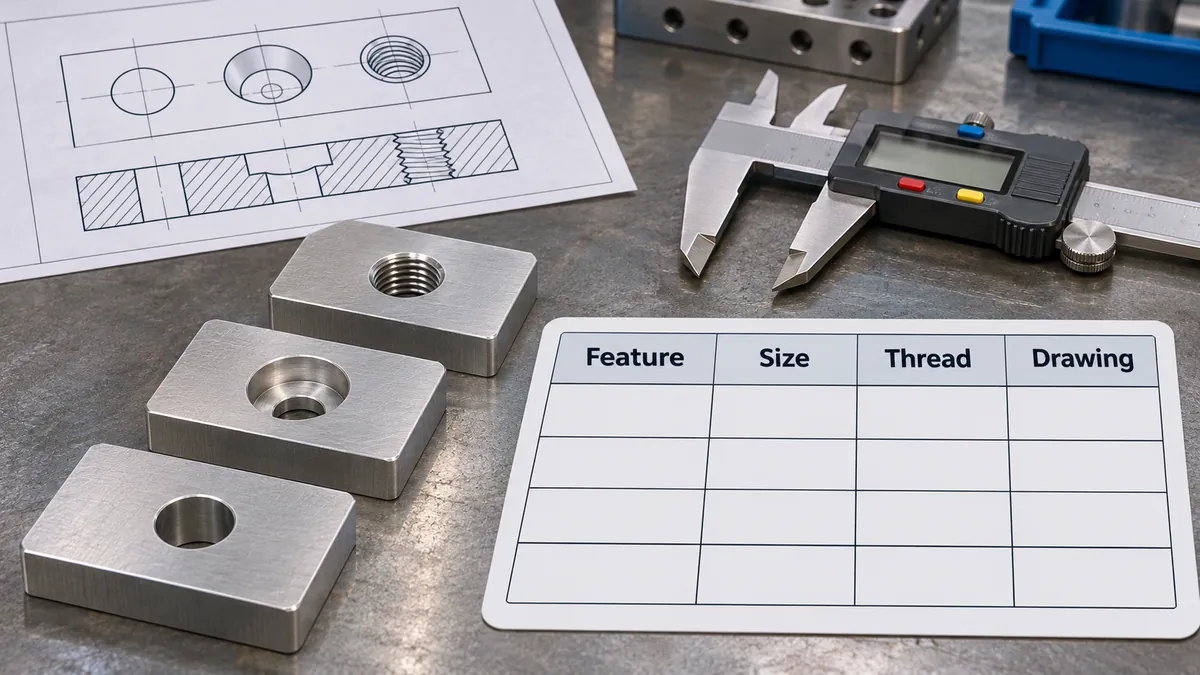
A convenient review method is to make a feature line for each axis instead of searching for one perfect noun:
| Drawing question | Record for each opening | Example of the information to clarify |
|---|---|---|
| Which part and face? | Component identifier and entry face | Mounting plate, front face |
| What extent? | Through or blind, plus the defined depth reference | Through the plate; or blind from the mounting face |
| What entry geometry? | None, chamfer, counterbore, countersink, or other specified seat | Recess matched to the selected fastener |
| What wall condition? | Plain, threaded, or insert-based | Thread in a named component, or clearance for a separate screw |
| What mating function? | Fastener, pin, passage, location, or other relationship | Identify the mating component and assembly condition |
| Where is it located? | Dimensions, datums, pattern, and orientation as required | Position relative to the part features used for assembly |
| What is inspected? | Characteristic, method, and acceptance source | Drawing revision and any agreed inspection record |
This is a completeness check, not a new standard. The exact dimensioning scheme must be agreed for the project. For additional context about a particular CAD application’s separated hole settings, consult the official Autodesk Fusion hole and thread feature documentation. A software menu is an illustration of design fields, not a mandatory drawing standard and not evidence that a supplier uses that software.
How to specify and review hole features for sourcing
How should buyers specify hole location and relationship?
An opening is not fully described by its type if its location is unclear. A useful drawing shows how the feature relates to the part and to the mating assembly. Depending on the design, the buyer may need dimensions from defined edges or datums, a pattern relationship, orientation, and a tolerance appropriate to the function. The article does not prescribe a particular geometric dimensioning standard; the project’s engineering authority should identify the applicable system.
For a bathroom accessory mounting plate, the relevant question may be whether the screw locations align with an installation template or mating bracket. For a home-storage component, the issue may be whether a pin, insert, or tube aligns with the adjoining part. These examples show why two holes with the same diameter can serve different roles and carry different positional requirements. A catalog-style list of names cannot substitute for the assembly relationship.
When a feature lies near a bend, weld, formed edge, or cosmetic face, the drawing should make the relationship visible enough for engineering and manufacturing review. A hole can be nominally correct in one flat view while its actual use is affected by the bend, joining sequence, coating, or assembled position. This does not mean a specific failure will occur. It means the buyer should review the feature in the actual part context rather than approve a disconnected diameter symbol.
Koitor’s existing discussion of hole and bend relationships covers that separate design interaction. Likewise, the secondary-operation RFQ guide addresses how additional processes should be discussed. Here, the point is to identify the hole feature and its location before those deeper questions are handled on the appropriate page.
A buyer can reduce interpretation gaps by sending the supplier the same controlled information set:
- Current drawing revision and the relevant view or section.
- Part number and the surface from which each depth is measured.
- Mating fastener, insert, pin, or component information when available.
- Which dimensions are functional and which are reference only.
- Required final condition, including finish or coating effects where relevant.
- Clarification of any assumed standard, thread series, or inspection basis.
- An explicit question list for unresolved features instead of an undocumented verbal assumption.
Which manufacturing and finish questions remain project-specific?
A drawing feature does not state the production method unless the project says so. Openings in metal hardware may be created by different methods depending on component geometry, material, thickness, tooling, quantity, finish, and the supplier’s verified capability. A drawing that defines a functional result may allow the manufacturer to propose a route, but the buyer should not assume that every supplier can produce every geometry by the same operation.
Sheet, tube, wire, cast, or assembled components have different constraints. A hole in flat sheet may be made before forming or at another stage; a tube opening and a threaded insert present different design questions from a tapped solid block. This article does not assert which route Koitor uses for a particular order. The actual component, equipment, sample, and approved process determine the answer.
Finishing can also affect the final feature. A coating, plating, polishing, or other surface treatment may change edge appearance or the fit between mating parts, depending on the process and requirement. A buyer should state whether dimensions are measured before or after finish when that distinction is material to acceptance. Avoid assuming that a standard hole name automatically accounts for coating thickness or final fit.
If the hole is close to a cosmetic surface, the acceptable edge condition may need explicit agreement. If it is near a weld or bend, the assembly and process sequence may affect access or inspection. If the opening drains, vents, or supports a load path, that functional purpose should be made clear. These are engineering review prompts, not predictions of a defect or a claim about Koitor’s production results.
The supplier discussion should distinguish three things: the designed geometry, the proposed manufacturing route, and the final acceptance evidence. A CAD image may show the geometry but not prove the manufactured size. A process description may explain a route but not demonstrate the final part. A sample may help confirm interpretation, but the buyer still needs to control the approved drawing and any relevant revision before production release.
What are common mistakes when using hole names?
The most common communication error is treating one word as if it answers every design question. “Blind” does not state whether the opening is threaded. “Tapped” does not say whether the feature is blind or through. “Countersunk” does not identify the exact mating fastener or establish that the head will sit flush. “Clearance” is incomplete if the mating screw and required fit remain unknown.
Other avoidable mistakes include:
- Using a visual mark as a complete specification. A circle in a view may not convey depth, recess shape, thread, or the intended mating part.
- Leaving the depth reference unstated. A value can be measured from the wrong face or interpreted as total depth rather than usable depth.
- Mixing an edge break with a fastener seat. A chamfer for deburring and a functional countersink do not have the same purpose.
- Specifying a thread without its scope. The feature may belong to an insert or another component, not the sheet itself.
- Ignoring the assembly stack. A hole that fits one plate may not align after several components are assembled.
- Copying dimensions from an unrelated fastener. The selected screw, applicable standard, and product design must agree.
- Assuming the intended process from the feature name. A hole callout describes a requirement; it does not by itself establish the shop’s operation.
- Treating a sample as a substitute for revision control. The approved sample and current drawing should be reconciled before release.
- Over-specifying a nonfunctional feature without reason. Extra dimensions or tolerances can create cost and inspection work without improving the assembly; the design authority should determine what matters.
A clear question is more useful than adding unexplained abbreviations. If a supplier proposes a different interpretation, record the clarification on the drawing or approved document so the same decision carries through quotation, sampling, production, and inspection.
How should importers review a hole feature before RFQ or sample approval?
Begin by identifying the buyer’s purpose, not by collecting an encyclopedia of hole names. Is the feature meant to let a fastener pass, provide a threaded engagement, seat a head, align a component, or create a passage? Then identify the dimension and evidence needed to confirm that purpose. This sequence lets the supplier respond to the real design requirement while making unknowns visible.
For a new drawing, ask the design team to mark critical versus reference dimensions and define the relevant mating components. If the design is still flexible, provide a sample, sketch, or controlled model and ask the supplier to list assumptions and questions. A supplier proposal should be reviewed by the buyer’s responsible engineer before a design decision becomes an approved specification.
During sample review, check the feature against the controlled revision and intended mating component. Verify the final finish condition if it affects fit or appearance. Document any change to depth, position, recess, thread, insert, or assembly. Do not treat a successful fit in one informal setup as proof of every tolerance or production-lot condition.
Before production release, align the quotation, drawing, sample approval, inspection plan, and purchase-order references. If those documents identify different hole versions, stop and resolve the mismatch. This is especially important after a design revision or a change to a screw, insert, plate thickness, finish, or assembly sequence.
What checklist helps clarify hole features in an RFQ?
Use this checklist to make a drawing review concrete. It does not require a buyer to specify every field for every part; mark what applies and identify what remains open.
- [ ] Part number, drawing revision, and component name are consistent.
- [ ] The view or section identifies the entry face and relevant opposite surface.
- [ ] Each opening is described by its extent: through or blind, with a clear depth reference if blind.
- [ ] Any recess is named by its geometry and tied to the actual fastener or seating purpose.
- [ ] Threaded, insert-based, plain, and clearance features are distinguished.
- [ ] The mating screw, pin, insert, or component is identified or listed as an open item.
- [ ] Functional position, pattern, and orientation are dimensioned using the project’s drawing system.
- [ ] The final finish condition and any relevant before/after-finish measurement basis are clear.
- [ ] The supplier’s proposed manufacturing assumptions are separated from the design requirement.
- [ ] Sample acceptance and production inspection refer to the same controlled revision.
- [ ] Unresolved questions have an owner and are recorded before order release.
How can Koitor Hardware support a drawing and sample discussion?
Koitor Hardware is a family-owned custom metal hardware factory focused on bathroom and home-storage hardware. Buyers can share a drawing, sample, component description, or unresolved feature question so the project scope can be discussed against the actual requirement. A supplier discussion can clarify what information is available, what requires engineering confirmation, and what assumptions should be recorded before a quotation or sample is approved.
This is a communication path, not a promise that every requested geometry, thread, tolerance, test, or production route is supported. The project-specific drawing and confirmed capability define the scope. A buyer evaluating a relevant accessory can review Koitor’s custom bathroom hardware manufacturing scope or the OEM home-storage hardware page while keeping product and commercial-page intent there.
When asking for project feedback, include the intended mating part, the opening’s purpose, current drawing revision, material and finish context, and the questions that remain unresolved. That gives both parties a concrete basis for discussing whether a clarification, updated drawing, sample, or alternate design review is appropriate. Any final engineering decision remains subject to the buyer’s design authority and the agreed production specification.
Häufig gestellte Fragen
Are through and blind holes separate from threaded holes?
Yes. Through and blind describe how far the opening extends relative to the specified material. Threaded describes an internal helical feature. A hole can be through and threaded, blind and threaded, or plain, depending on the design. The drawing should state the relevant combinations rather than assume one word explains all of them.
Is a countersink a separate hole type?
It is a recess geometry associated with an opening. It can be combined with a through or blind condition and may be paired with a plain, clearance, or threaded feature as the design requires. The actual fastener and project dimensions determine whether the geometry is suitable. See the dedicated counterbore-versus-countersink page for that narrower comparison.
Does “blind depth” always mean usable thread depth?
No. Total hole depth, straight-sided depth, and usable thread engagement can be different quantities. The drawing or specification should define the depth that matters and the reference face. The correct values depend on the component design and must not be inferred from a generic rule.
Can a sheet-metal part have a threaded hole?
It may use a threaded feature through a suitable design, such as a separate insert, but the appropriate construction depends on thickness, material, loading, assembly, and supplier capability. The buyer should identify which component contains the thread and request confirmation of the proposed construction rather than assume a thin sheet is directly tapped.
Does a hole label prove the supplier can make the feature?
No. A label communicates design intent, not an individual supplier’s confirmed capacity or finished-part conformity. Confirm the project geometry, proposed manufacturing route, sample or other agreed evidence, and inspection basis with the responsible parties.
What should a buyer do when the drawing uses an unfamiliar abbreviation?
Ask the design authority or supplier to expand the term in writing and point to the relevant view, feature, and mating component. Confirm the interpretation against the current revision before quotation, sample approval, or production release. Do not rely on an unverified symbol from a different drawing system.
Arbeiten Sie mit Koitor Hardware zusammen
If a hole feature is unclear on a bathroom or home-storage hardware drawing, share the current revision, part context, mating component, and the specific question. Koitor Hardware can discuss the available project information and clarify the scope that needs review. The goal is to make assumptions visible before they become quotation, sample, or production misunderstandings.
Discuss a drawing, sample, or hardware feature with Koitor Hardware.
OEM / EIGENE MARKE
Verwandeln Sie diesen Beschaffungsleitfaden in ein Produktdossier
Teilen Sie uns Ihr Zielprodukt, die Größe, die Oberflächenausführung, die Bestellmenge und Ihre Verpackungsanforderungen mit. Ihr Team erhält vor der Angebotserstellung eine praxisorientierte Prüfung der Herstellbarkeit.


 English
 Español
 Português
 Français
 Deutsch
 العربية