
Surface finish symbols communicate a surface-texture requirement on technical product documentation, but the symbol alone is not a complete acceptance rule. A buyer must identify the drawing standard and edition, read the full callout, determine which surface it applies to, and confirm the parameter and method that define acceptance. A symbol is not a photograph of the desired appearance, and it does not prove that a part has been measured or meets the requirement.
Start with the drawing standard and edition
A surface texture symbol should be read in the context of the drawing convention that governs the part. Different standards and editions can use similar graphical ideas but differ in rules, placement or associated fields. A familiar chart found online may describe a legacy convention rather than the one named by the current drawing. Before interpreting a glyph, look for the standard reference, revision and any company-specific drawing practice stated in the title block or specification.
ISO 21920-1:2021 is the published ISO edition for profile-method surface-texture indication. The official ISO catalog describes its scope as rules for indicating surface texture in technical product documentation by graphical symbols and says that it does not cover population requirements. The catalog currently lists the edition as published and also identifies a revision project in progress. The prior ISO 1302:2002 edition is marked withdrawn. These status details show why a buyer should verify the named edition rather than rely on an undated chart. They do not provide access to the complete normative text or authorize reconstructing every symbol-placement rule from a short summary.
If a drawing only shows a symbol without naming its convention, ask the design owner which standard and edition to use. If the drawing is based on a customer specification or legacy CAD library, preserve that context rather than silently replacing its symbols with a newer-looking chart. Where supplier and buyer practices differ, agree on the interpretation in writing before production. A short clarification is safer than assuming both parties assign the same meaning to every mark.
This article is an interpretation aid for buyers reviewing metal hardware drawings. It does not reproduce a normative symbol chart, set a default roughness value or tell a manufacturer which finish to use. The correct requirement depends on the controlled document and product function.
What a basic symbol can communicate
In common legacy introductory conventions, a basic surface-texture symbol identifies that a surface-texture requirement applies. An added bar is commonly used to indicate that material removal is required; an added circle is commonly used to indicate that material removal is prohibited. These descriptions are useful recognition cues, not a substitute for checking the drawing’s named standard and edition. Do not assume that an internet graphic using one convention fully represents a current standard or every placement rule.
The symbol family may be accompanied by text, values, lines or other fields that define the requirement more completely. Depending on the applicable convention, a callout can include a parameter and limit, an allowance or process note, direction/lay information, sampling or evaluation details, or a reference to another document. The buyer’s job is not to infer every field from an icon. It is to identify which fields appear, what the drawing says they mean under the stated convention, and what information remains missing.
A bar or circle does not specify a numeric roughness value by itself. Nor does a basic symbol say that a surface is polished, brushed, coated or visually flawless. Process names and texture requirements answer different questions. A polishing note may describe a manufacturing operation; a texture callout states a technical surface condition under its applicable convention. If the requirement is appearance, include the relevant visual criteria separately rather than assuming a numerical texture parameter captures color, scratch direction, gloss or cosmetic uniformity.
| Drawing element | What it may identify | Was dies für sich genommen nicht beweist | Buyer action |
|---|---|---|---|
| Basic texture symbol | A surface-texture indication applies under a convention | A specific Ra value, finish process or acceptance result | Find the named standard and associated fields |
| Material-removal mark in a legacy convention | Removal is required under that convention | That polishing or grinding alone will meet a numeric requirement | Confirm the complete callout and required inspection |
| Removal-prohibited mark in a legacy convention | Material removal is prohibited under that convention | That the as-supplied surface meets the design function | Clarify the intended surface and permitted operations |
| Parameter/value field | A stated texture parameter and limit may apply | That other parameters or visual criteria are also controlled | Confirm units, parameter, limit and surface location |
| Process or lay note | A process or direction may be stated | That the process name guarantees measured texture | Treat it as an additional instruction, not a substitute for acceptance |
| Surface-zone marking | Which face or area the callout concerns | That unmarked surfaces share the same requirement | Mark relevant faces and clarify defaults from the standard |
The matrix is a buyer’s reading checklist. It intentionally avoids showing proprietary or normative symbol geometry and does not assign default values. If the callout is incomplete, unclear or inconsistent with the part’s function, request a drawing clarification.

Read the callout field by field
Identify the parameter
A drawing may specify a profile texture parameter such as Ra or another parameter. Do not assume “surface finish” automatically means Ra. A parameter measures a defined aspect of a profile or surface under a measurement method; different parameters are not synonyms and cannot be substituted without approval. If the symbol contains a value, check which parameter it belongs to, whether the unit is stated or established by the drawing convention, and which limit or evaluation condition applies.
Avoid taking an Ra value from an online “typical finish” chart and applying it to a new product without design approval. A value that appears familiar may not match the function, surface, measurement approach or standard edition of the current drawing. If the design team wants a specific texture, it should define the parameter and limit under an identified convention. The supplier should quote to that controlled requirement or raise a question if it cannot interpret it.
Locate the required surface
A callout may apply to a particular face, zone or feature rather than every surface on the component. Review leader lines, arrows, surface marks and notes together with the part views. If the drawing has several faces with different roles, identify which ones are visible, mating, sealing, sliding or otherwise functionally important. A finish symbol without a clear location can leave a supplier unsure which surface to inspect or process.
For a custom bathroom or home-storage part, a face may be hidden after assembly while another face remains visible. Those faces can have different requirements. A drawing should make that distinction explicit where it affects appearance or function. Do not assume a single note controls every face, especially when the symbol is attached to one view or feature.
Interpret process and removal notes carefully
Some symbol conventions distinguish whether material removal is required or prohibited. Such a mark is not a full process specification. If the drawing names grinding, polishing, machining or another operation, treat that as an additional process instruction and confirm that the resulting surface criterion is still defined. A process can produce different outcomes depending on abrasive, tooling, operator, material, sequence and inspection. Conversely, the same texture target may be achieved by different processes if the design permits alternatives.
If a removal-prohibited instruction conflicts with a later finish operation, ask the design owner which requirement controls and why. Likewise, if the drawing requires removal but gives no measurable result, determine whether a process note or a texture criterion is intended. Do not resolve conflicting notes by choosing the easiest manufacturing route without approval.
Check direction or lay only when it matters
A directional finish can affect appearance, tactile feel or the way a surface interacts with another component. If direction matters, the drawing or specification needs to identify it under the applicable convention. A texture symbol alone does not necessarily mean the product should have a particular brushed grain direction. Do not substitute a roughness value for a directional appearance requirement.
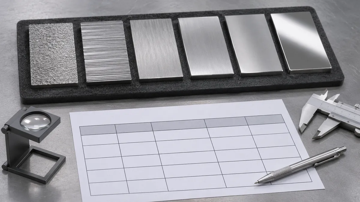
For visible surfaces, a reference sample, controlled image or written cosmetic description may be useful alongside the technical callout. These materials should clarify appearance, not redefine the measurement standard unintentionally. If a sample is the governing reference, identify it and describe how it relates to the drawing revision. A photograph may help identify a face or visual direction but cannot supply a reliable measured value.
Separate drawing interpretation from measurement acceptance
Reading a symbol is only the first step. The buyer also needs to know how the surface will be evaluated. A numerical profile requirement depends on the specified parameter and measurement conditions. A visual inspection, tactile check or photograph may help assess cosmetic appearance, but each answers a different question from a measured profile result. Do not claim that a visual check proves an Ra value or that one instrument reading proves every aspect of surface function.
A complete acceptance plan should identify, as applicable, the surface zone, parameter, limit, units, measurement method or reference standard, sampling plan, instrument access and required record. Only include fields required by the product and contract; a basic cosmetic surface may not need a complex metrology plan. If the requirement is functionally critical, the product engineer should define the relevant parameter and verification method rather than asking a supplier to guess from a symbol alone.
The measurement plan should also match the geometry. A small recess, narrow edge, curved wire or inaccessible feature may require a different inspection approach than a broad flat panel. This is not a reason to loosen a requirement automatically. It is a reason to confirm that the specified method can reach the surface and that the parties understand how results will be compared. If the location cannot be measured with the proposed method, agree on an alternate method before accepting the product.
Inspection records should connect the result to the part number, drawing revision, surface location, parameter, method and sample. A number without a location or method can be difficult to interpret. Likewise, a report that measures one sample should not be represented as proof of every surface in a lot unless the agreed sampling plan supports that conclusion. The buyer should define what the record covers and retain it with the corresponding order or approval.
Do not confuse the callout’s population scope with a batch acceptance plan. ISO’s catalog explicitly notes that ISO 21920-1 does not cover population requirements and points to a separate standard for that subject. That distinction means the symbol rules and the lot-sampling decision should be treated as related but separate parts of the quality plan. A buyer should identify the applicable requirements rather than assuming a drawing symbol defines how many units must be sampled.
A practical drawing-review workflow
- Find the governing standard. Check the title block, specification and contract for the standard and edition.
- Identify the symbol convention. Determine whether the drawing uses a current or legacy practice and whether a company note modifies it.
- Read every associated field. Record the parameter, value, unit, limit, process, lay or other stated information.
- Locate the affected surface. Trace leaders and marks to the correct face, zone or feature.
- Separate measured and cosmetic needs. State numerical texture and visual appearance separately when both matter.
- Confirm inspection feasibility. Make sure the method can access the surface and address the intended characteristic.
- Resolve gaps before quotation or release. Ask the design owner for clarification rather than supplying an assumed default.
- Keep evidence with the revision. Link approvals and reports to the part number, drawing revision and inspected area.
This sequence is useful when a supplier receives an older drawing, a customer-provided symbol chart or a note that conflicts with a modern CAD library. Preserve the source convention and ask for the missing reference. Do not redraw an unfamiliar symbol from memory; the drawing owner should approve any changed notation.
Manage drawing revisions and supplier questions
Surface texture notes are easy to lose when a drawing is converted between CAD systems, copied into a quotation spreadsheet or recreated from a raster image. A symbol may be simplified, moved away from its surface, or detached from a note that identified the governing standard. When a supplier asks for clarification, compare the issued drawing with the source file and confirm that the callout survived the transfer. If the mark is illegible, request a clean controlled drawing rather than relying on a guessed symbol from a screenshot.
The design owner should answer technical interpretation questions; the buyer should make sure the response becomes part of the approved order record. If the drawing changes, issue a new revision and state whether the surface requirement changed or only its presentation was corrected. The supplier should identify the revision used for the quote and any sample. This simple version control helps prevent one party from using a legacy chart while another applies a new template.
When a standard is revised or replaced, do not automatically convert every existing drawing. Determine which edition the contract or customer specification calls up, whether the change is editorial or affects the interpretation, and who has authority to approve an update. A current official catalog can show publication and lifecycle status, but it does not replace the standard text or the buyer’s engineering assessment. If the product is subject to a customer-specific requirement, that contract may govern until formally changed.
The supplier should raise uncertainty before processing the surface, especially where the note could change the sequence or prohibit an operation. The buyer can respond with a clarified callout, a reference to the governing specification, or an approved cosmetic sample. Keep the question, decision and drawing revision together. An email that says “use the usual finish” may not be reproducible for another supplier or reorder unless the technical requirement is also captured in the controlled documents.
Match verification evidence to the requirement
Before accepting an inspection report, check whether it records the intended characteristic. A profile texture reading should identify the parameter, method and location; a photograph should identify the face and viewing condition; a process traveler can show that an operation was performed but not necessarily that the result meets a numeric limit. These records complement one another rather than proving the same thing. Request only the evidence that supports a defined acceptance decision.
If several surfaces are listed, make the sampling plan clear. The report should not leave the reader guessing whether it covers one representative surface, every marked zone, or a small subset chosen under a lot plan. For a sample approval, state whether the result applies only to the submitted part or also informs a production control. For recurring orders, define the records to retain and the party responsible for review. These controls make acceptance auditable without implying that every component requires identical metrology.
An instrument result also needs context. Measurement access, stylus direction, filter, cutoff, instrument condition and operator practice may matter for a specific method; the applicable standard and engineering specification determine which settings are appropriate. This article does not prescribe those settings. When the surface is narrow, curved, soft or otherwise difficult to measure, ask the responsible quality or engineering team to approve a practical method before the supplier reports a pass/fail value.
Hypothetical hardware example
Imagine a formed metal bracket used in a bathroom storage product. One broad face is visible after assembly, a contact surface mates with another component, and a hidden interior face is not visible to the user. A drawing shows a surface-texture symbol on the visible face but does not state an edition or identify whether the number refers to Ra. A supplier may reasonably ask whether the note is a measured requirement, a process preference or an appearance instruction.
The buyer should locate the symbol’s source convention, confirm its complete meaning and identify the face to which it applies. If a numerical texture requirement is needed, the design owner should name the parameter, limit and inspection approach. If the concern is appearance, the buyer can add a cosmetic description or approved reference while keeping the measurement requirement separate. The supplier should then confirm which operation is included and how it will record acceptance.
This example is hypothetical. It is not a Koitor customer case, measurement result, standard interpretation for every drawing or claim that a specific finish is required. It demonstrates how to turn an ambiguous mark into a controlled conversation.
Common drawing-review mistakes
- Using an undated symbol chart. Confirm the standard and edition named by the drawing.
- Treating a legacy convention as current by default. Identify whether the drawing refers to a withdrawn edition or a company practice.
- Assuming a symbol means Ra. Read the associated parameter rather than supplying a familiar value.
- Confusing process with result. “Polished” or “ground” does not automatically define a measurable texture.
- Applying one note to every face. Trace the leader and state the applicable surface area.
- Using a photo as measurement proof. Appearance references and profile measurements serve different purposes.
- Treating a single sample as a lot plan. Define sampling and population acceptance separately.
- Copying numerical defaults from a website. Use the contractually applicable standard and approved engineering requirement.
- Ignoring method access. Confirm the instrument can reach the specified area and evaluate the intended characteristic.
- Silently correcting an ambiguous drawing. Send a formal clarification and preserve approval with the revision.
Häufig gestellte Fragen
What do surface finish symbols mean?
They communicate a surface-texture requirement under a drawing convention. The complete meaning depends on the named standard and edition, symbol details, associated fields and the surface location.
Does a surface finish symbol specify Ra?
Not necessarily. Read the parameter and value shown in the callout. Do not infer Ra or a default value from the phrase “surface finish.”
What does a bar or circle added to a symbol indicate?
In common legacy introductory conventions, a bar is associated with required material removal and a circle with prohibited material removal. Confirm the drawing’s actual standard and edition before applying that explanation.
Is ISO 1302 still the current ISO standard for surface texture indication?
The ISO catalog lists ISO 1302:2002 as withdrawn and ISO 21920-1:2021 as published; it also shows a revision project for ISO 21920-1. Confirm the edition named by the drawing and check the official catalog for current status.
Does a roughness value describe the visual appearance?
A profile parameter does not fully define color, gloss, scratch direction or every cosmetic characteristic. If appearance matters, state it separately and agree on the visual reference or inspection conditions.
Does the symbol define how many parts to inspect?
Not by itself. A surface-texture indication and a lot-sampling or population requirement are separate controls. Define the sampling plan in the applicable quality documentation.
What should I send a supplier when the symbol is unclear?
Send the controlled drawing and revision, the referenced standard and edition if known, the affected surface, the intended function, and the unresolved parameter or appearance question. Request a written clarification before production.
How can Koitor help review a surface callout?
Koitor Hardware is a family-owned custom metal hardware factory with approved drawing and sample communication. Buyers can share the relevant callout, surface location and project requirement for discussion. This does not imply accredited metrology or standards-conformity services.
Sources and scope
- ISO 21920-1:2021 official catalog
- KEYENCE: Surface Finish Symbols and Chart
- KEYENCE: Roughness Symbols
Scope note: This is a buyer’s drawing-reading guide, not a substitute for the applicable standard text. ISO catalog status was checked on 2026-11-19; verify the named edition and current project status before applying a requirement. No numerical default, measurement result or metrology capability is claimed.
Clarify a surface texture callout on a hardware drawing
Share the controlled drawing, standard reference, affected surface and unresolved finish or measurement question. Koitor can discuss the surrounding custom metal hardware project within its confirmed scope.
OEM / EIGENE MARKE
Verwandeln Sie diesen Beschaffungsleitfaden in ein Produktdossier
Teilen Sie uns Ihr Zielprodukt, die Größe, die Oberflächenausführung, die Bestellmenge und Ihre Verpackungsanforderungen mit. Ihr Team erhält vor der Angebotserstellung eine praxisorientierte Prüfung der Herstellbarkeit.


 English
 Español
 Português
 Français
 Deutsch
 العربية