
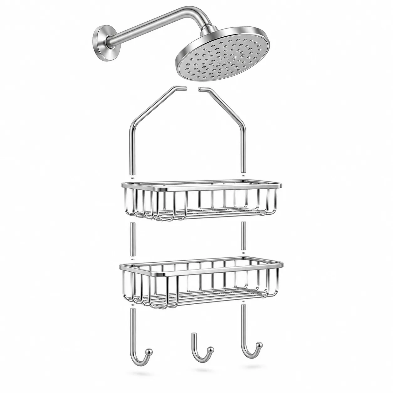
An exploded view drawing shows components of an assembly separated from their assembled positions so a reader can understand how the parts relate. The separation is a visual arrangement: the gaps do not automatically represent real operating clearances, final dimensions, or a valid assembly sequence. Callouts, item numbers, a parts list, and detail drawings may connect the illustration to controlled product information, but their exact meaning depends on the document set. Buyers should use the exploded view to understand component relationships, then use the assembly definition and dimensioned drawings to confirm fit, quantity, orientation, and approved revision.
What does an exploded view drawing show?
An exploded view drawing depicts parts or groups of parts moved away from their assembled positions while maintaining enough orientation to show how they fit together conceptually. Lines, balloons, labels or item numbers may help identify which components belong in the assembly. Onshape’s CAD documentation describes creating an exploded view by moving parts or groups through recorded translation or rotation steps; the resulting representation is an edited view of an assembly model, not a separate physical test of the parts.
A DraftSight explainer from SOLIDWORKS similarly describes the illustration as a way to represent relationships between components. These sources support the general meaning, but a view’s purpose can vary: it may support product explanation, an assembly instruction, parts identification, servicing, or design review. The title block, legend, linked parts list and surrounding documents tell the buyer how the specific view is intended to be used.
| Visible item | What it can help communicate | What it does not automatically prove |
|---|---|---|
| Separated components | Which parts belong to the assembly and their relative orientation | Actual gap, clearance or installed spacing |
| Explode line | A visual relationship or movement path in the illustration | Required assembly sequence unless the document says so |
| Balloon or item number | A link to a numbered parts list or callout | Complete specification, supplier or purchasing scope |
| Parts list | Names, identifiers or quantities as defined by that document | Every material, tolerance, finish or acceptance requirement |
| Shaded or rendered appearance | General visual form and orientation | Exact surface finish, color, dimensions or production condition |
| Detail drawing reference | Where controlled geometry may be specified | That the referenced drawing is current unless revisions align |
The table is a reading framework rather than a prescribed drawing standard. Some documents use different symbols or conventions. If an exploded line or callout is ambiguous, refer to the drawing legend or ask the document owner; do not infer a universal meaning from an example found online.
Why are components spaced apart in the illustration?
Components are spaced so they can be seen separately. The visual distance helps the reader distinguish parts, follow an interface, and notice a fastener or intermediate component that might be hidden in the assembled view. It is selected for legibility and may be adjusted to prevent overlap. An exploded image can therefore show a large gap between parts even if they touch or sit close together in the assembled product.
This distinction matters when a buyer compares a drawing to a sample. The exploded distance is usually not a dimensional callout. It does not specify the installed gap, movement allowance, adhesive thickness, screw engagement, or clearance between parts. Those conditions require the relevant section, dimension, tolerance, assembly note, or other controlled requirement. A perspective rendering can also make dimensions look different because of view angle or display scaling.
A bathroom rack provides an accessible hypothetical example. Imagine an outer frame, two baskets, mounting brackets and screws shown as separate items. The exploded view can help identify that a bracket connects the frame to a wall mount and that the baskets attach to the frame. The drawn gap between a basket and its support is only an illustration unless a dimension or instruction says otherwise. The example does not depict an actual Koitor product configuration or confirm that any particular design is suitable.
A buyer reviewing an exploded representation should distinguish three questions:
- Identity: Which component is this, and which part-list item corresponds to it?
- Relationship: Which other part does it connect to or align with?
- Requirement: Which controlled document defines the fit, dimensions, orientation, finish and assembly method?
The image can answer the first two partially and visually. The third typically depends on the broader document set and engineering decision. Do not ask the exploded illustration to carry details that are not actually shown or referenced.
Does an exploded view show the assembly order?
Not necessarily. The relative position of parts may suggest a possible sequence, but the illustration alone does not guarantee the intended order of assembly, required tools, fastening torque, adhesive cure, safety steps, or inspection checkpoints. Some exploded views are designed only to identify components. Others are included as part of step-by-step instructions. The document needs to make that role explicit.
If the drawing is meant to communicate sequence, look for ordered steps, arrows or numbered actions and read the corresponding instruction text. Check whether the sequence accounts for access: a screw or clip may need to be installed before a neighboring component blocks the tool. A visually intuitive order may not be the actual process. Assembly documentation should describe the controlled action, not leave operators to infer order from the spacing of the parts.
The distinction also matters in sourcing. A buyer may request an exploded view during product development to explain component relationships, but still need a separate assembly instruction for production, packing or end-user installation. Koitor’s existing bathroom rack assembly-instruction guide addresses the instruction question. For multilingual documents, see the separate multilingual instruction checklist. This article explains how to read the view, not how to create a complete instruction manual.
When sequence is important, the buyer should identify the intended user: factory assembler, quality inspector, packer, installer, service technician or consumer. Each may need different content. A production sequence can specify internal assembly operations, while a consumer guide may show only installation or maintenance steps. The buyer should not assume that one exploded image is sufficient for every audience.
How do item balloons connect to a parts list?
An item balloon or callout can connect a visible component to an item in a parts list, bill of materials or assembly record. That connection is useful only when numbering is consistent and the list belongs to the same product revision. A balloon number is not a complete product specification by itself. The referenced list may include a description or part number, but material, finish, dimension, purchase source and revision can live in other controlled records.
For procurement, compare the components shown with the parts list and BOM scope. Identify whether a fastener, insert, bracket, cap, pad, adhesive component or packaging item is included in the order or supplied separately. A visual item can appear in a drawing even if it is not part of the supplier’s quotation. Conversely, an item may be described in the BOM but hidden behind another part in the selected view.
A useful cross-check records:
| Comprobar | Acción del comprador | Por qué es importante |
|---|---|---|
| Balloon coverage | Confirm every purchasing-relevant component is numbered or otherwise identified | Prevents an unreferenced visual item from being mistaken for a supplied part |
| Parts-list mapping | Match each number to a part number and description | Separates visual identity from procurement identity |
| Quantity | Confirm quantity per assembly and any spares separately | An illustration may show one instance while the BOM quantity differs |
| Scope | Check who supplies each component | Avoids assuming included hardware or accessories |
| Revision | Match view, parts list and BOM revisions | Prevents old item numbers from being applied to new geometry |
| Detail source | Follow references to component drawings or specifications | Finds the actual dimensions and acceptance requirements |
This is not a full BOM-management procedure. Koitor’s existing article on engineering BOM, manufacturing BOM and kit differences covers the distinct question of how those records differ. Here, the key point is that a balloon and list make the exploded view traceable; they do not automatically merge all purchasing and manufacturing data into the picture.

Which document defines dimensions and interfaces?
A dimensioned component or assembly drawing usually carries the actual controlled geometry and tolerances, while the exploded view primarily clarifies how components relate. The governing document can vary by project and company system, so the buyer should follow the title block, document references, contract and approved revision. A view without dimension annotations does not create a dimension requirement merely because its parts look proportioned.
The assembled interface is where fit questions become concrete. A bracket-to-frame connection, screw-to-insert engagement, basket-to-rail fit, or pad-to-surface interface may need a dedicated dimension, section, fastener callout or approved sample. If two parts appear to meet in the exploded drawing, that does not specify the interface tolerance. If the parts appear separated, that does not establish installed clearance. Refer to the controlling detail and identify which surfaces or features are functional.
A buyer can use a simple mapping:
- Exploded view: component identity and visual relationship.
- Assembly view: components shown in their assembled arrangement.
- Detail drawing: controlled geometry and dimensions for a part or interface.
- Parts list/BOM: component identity, quantity and record relationship as defined by the project.
- Assembly instruction: action sequence and user-facing steps where required.
- Inspection plan or acceptance record: agreed checks and evidence for the order.
The names above describe common document roles, not a mandatory package or official standard. A project may combine several roles or use different terminology. What matters is that the buyer can identify the source for every required decision and confirm that documents refer to the same revision.
When the submitted files omit a needed detail, list it as an open question. For example: “The exploded view identifies the bracket and frame relationship; please provide or confirm the drawing that defines the mating slot and fastener requirement.” That is safer than measuring a screenshot or estimating a dimension from the drawn gap. See Koitor’s guide to preparing drawings and samples for an OEM discussion for the separate document-handoff topic.
How to apply exploded-view information during sourcing
What revision information should buyers check?
An exploded view can become misleading if its item numbering, component shapes or references no longer match the current parts list or drawing. Confirm that the assembly view, component details, BOM, sample and quotation use the intended revision. If the view has no visible revision or issue identifier, ask the document owner how it is controlled before using it for approval or production communication.
A revision check should not stop at the file name. Compare the title block, issue history or approved document record, then confirm that linked files and part numbers still match. File names such as “final,” “final2” or “latest” are not reliable revision controls on their own. If a drawing changes after sample approval, record which interfaces or list entries changed and whether the exploded view must be updated to maintain an accurate visual relationship.
Koitor’s separate article on drawing revision control addresses change tracking in more depth. This guide keeps the emphasis on how a reader uses the current exploded view alongside the rest of the document set. Neither a visually plausible illustration nor an older approved sample resolves a mismatch between the current order revision and its parts list.
If the exploded drawing was created from a model, ask whether the model and drawing are linked to the same release, but do not assume a CAD file is the contractual source merely because it is editable. The project documentation should state which representation governs dimensions and changes. Preserve the approved export or controlled file reference with the order record so a later reviewer can tell which view was reviewed. When a part is intentionally moved for clarity, the revision record should make clear that the presentation changed without suggesting its physical geometry changed. This distinction helps procurement and quality teams interpret a new illustration without confusing a layout edit with a product engineering change.
What common mistakes occur when interpreting exploded views?
- Measuring the visual gap. The displayed spacing is arranged for clarity and does not automatically equal installed clearance.
- Assuming spatial order equals assembly order. A drawing may identify parts without specifying sequence or tool access.
- Treating a balloon as a full specification. Item numbering points to a list; it does not by itself state material, finish or tolerance.
- Assuming every depicted item is included. Procurement scope must be checked against the quote, BOM and purchase order.
- Ignoring hidden interfaces. A perspective view can hide the feature that actually controls fit.
- Using the view instead of the detail drawing. Functional dimensions belong in the controlling engineering information.
- Mixing revisions. A current illustration paired with an old BOM can create wrong quantities or part identities.
- Treating a render as evidence of finish or color. Display settings and rendering do not necessarily represent the approved surface.
- Using one view for every audience. Production, installation, service and consumer instructions have different communication needs.
- Assuming a CAD-generated view is automatically correct. The underlying model and the selection of parts still need review by the responsible design owner.
These are interpretation risks, not claims that every exploded drawing contains errors. If information is missing, keep it visible as an unresolved item and request the document that controls it. Avoid silently adding a dimension, sequence or inclusion assumption based on how the illustration looks.
How can importers review an exploded view before approving a sample?
Start by stating what decision the image is supposed to support. If the goal is to identify parts, check the callouts and list. If the goal is to review an interface, locate its dimensioned detail. If the goal is assembly, obtain the instruction and sequence information. If the goal is product explanation, confirm that the illustration remains faithful to the approved configuration but do not treat it as a tolerance record.
Then compare the representation with the current sample and controlled documents. Confirm component identities, quantities, interfaces and revisions. Note any part that appears in the view but is missing from the list, any listed part that cannot be identified, and any relationship that remains ambiguous. For a sample approval, describe the observation rather than using the exploded spacing as a measured criterion.
A supplier or buyer may propose a clearer view, but any visual update should preserve the correct part identities and references. If a component is repositioned only for illustration, do not imply that the new position is a design change. If geometry or a part number changes, route it through the project’s normal drawing and approval process. A visual aid should make the controlled design easier to understand while remaining subordinate to the source records that define it.
An exploded view also should not be used to infer manufacturability without the relevant production information. It may reveal that parts connect, but not necessarily the joining method, fixture access, sequence, dimensional tolerance, finish allowance or inspection method. Those questions require the appropriate engineering and supplier review. Koitor can discuss a relevant drawing or sample within confirmed project scope as a family-owned custom metal hardware factory; the image alone does not prove a specific process or capability.
What checklist helps review an exploded drawing?
Use the checklist to identify what the visual communicates and what must be confirmed elsewhere. Mark each point as verified, not applicable or open.
- [ ] Product name, assembly identifier and drawing revision are visible or traceable.
- [ ] Each purchasing-relevant component is identified by callout or another agreed method.
- [ ] Balloons map correctly to a current parts list or BOM.
- [ ] Quantities per assembly are confirmed outside the visual spacing.
- [ ] Supplier and buyer scope for fasteners, inserts and accessories is clear.
- [ ] The drawing’s purpose is stated: identification, assembly, service, design review or presentation.
- [ ] Actual dimensions and tolerances are referenced to the controlling detail drawing.
- [ ] Interfaces and mating parts are reviewed in assembled context.
- [ ] Any assembly sequence is supported by ordered instructions rather than inferred from layout.
- [ ] Surface finish and color are confirmed from the approved specification or sample.
- [ ] Exploded separation is understood as illustrative unless a dimension says otherwise.
- [ ] The sample, drawing, parts list, quotation and order use a consistent revision.
- [ ] Missing or conflicting information is recorded as an open question before approval.
Preguntas frecuentes
Does an exploded view drawing show actual part spacing?
Not unless the document explicitly dimensions or defines that spacing. Components are commonly separated to make them visible. Use the assembled view, detail drawing, tolerance or approved specification for real clearance and interface requirements.
Does an exploded view tell an assembler what to do first?
Not always. A view may simply identify components. Use ordered instructions, step numbers or assembly notes when sequence matters. Do not infer tools, tightening requirements or safety steps from the visual arrangement alone.
Is an exploded view the same as a bill of materials?
No. The view is an illustration of component relationships; a BOM or parts list is a structured record of item identity and quantity according to the project. The illustration may link to the list through balloons, but it does not replace the full purchasing or manufacturing record.
Can I approve a product using an exploded drawing alone?
Only if the decision concerns something the drawing actually communicates and the project’s approval process accepts it for that purpose. Fit, dimensions, finish, supplied scope and performance usually require other controlled evidence or specifications. Ask which document controls each criterion.
What if an exploded view and a sample disagree?
Identify the current drawing revision and the intended sample status, record the discrepancy and obtain a written resolution from the responsible design owner. Do not choose one source informally or measure illustrative spacing to settle a geometry disagreement.
Why are some exploded views shown without dimensions?
Their purpose may be to communicate which parts belong together rather than specify geometry. The dimensional requirements may be on separate part or assembly drawings. Follow the document references and request missing details if they are needed for the decision at hand.
Trabaja con Koitor Hardware
If an exploded view is part of a bathroom or home-storage hardware project, share the current assembly drawing, parts list, related detail drawings, sample status and the question the visual should answer. Koitor Hardware can discuss relevant project information within confirmed manufacturing scope. The view, supplier proposal and buyer’s controlled specification should remain aligned before sample or production approval.
Discuss a hardware drawing or sample with Koitor Hardware.
OEM / MARCA BLANCA
Convierte esta guía de abastecimiento en un resumen del producto
Indícanos el producto que deseas, el tamaño, el acabado, la cantidad del pedido y los requisitos de embalaje. Tu equipo recibirá un análisis práctico de la viabilidad de fabricación antes de recibir el presupuesto.


 English
 Español
 Português
 Français
 Deutsch
 العربية