
Before a factory interprets a multi-view hardware drawing, the buyer and drawing issuer should confirm whether the views use first-angle or third-angle projection and identify the base view. A first angle vs third angle projection manufacturing drawing can place projected views in different positions relative to the base view, so a buyer should verify at least one asymmetric feature against an agreed isometric view, model or physical reference. Do not infer the convention from the buyer’s country, page language, measurement units or a cropped screenshot. Resolve ambiguity before quotation, tooling or sample release.
Why Does Projection Angle Matter to an OEM Buyer?
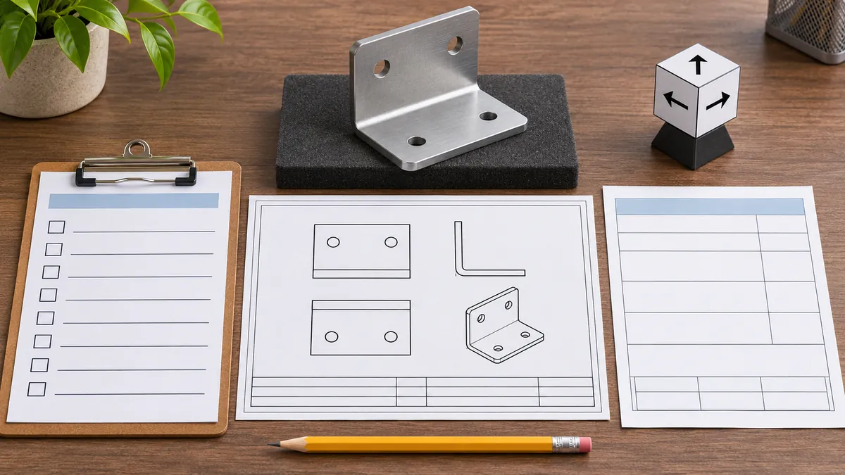
Orthographic drawings show a three-dimensional part through multiple two-dimensional views. The view arrangement tells the reader which side is represented in each view. Autodesk’s Fusion drawing documentation explains that first-angle and third-angle projection differ in where projected views are placed relative to the base view. A drawing can still be dimensioned yet be misunderstood if its view convention is missing, unclear or disconnected from the part’s physical orientation.
For symmetric shapes, an orientation mistake may not change the visible geometry. For an asymmetric bracket, mounting plate or storage assembly, it can reverse the side of a notch, bend, hole pattern, welded tab or attachment feature. That may alter how the part meets a wall, mating component or adjacent assembly. The manufacturing consequence depends on the actual part; a buyer should not assume every reversed view creates a defect. The risk is that different people can produce or approve different interpretations of the same drawing.
Projection convention is only one part of drawing interpretation. It does not define the datum scheme, tolerances, material, finish, revision precedence or every detail needed to produce the product. Keep those topics in their own controlled fields. For broader preparation, use the project’s RFQ file-format and drawing handoff guide y drawing and sample preparation checklist. This article concentrates on the direction from which the views are read and how one physical-side feature can expose a mismatch.
How Do First-Angle and Third-Angle Views Differ?
The base view is the starting view, often selected to show the part’s most useful shape. Other views are projected from it. In third-angle projection, a projected view is placed on the same side of the base view as the direction from which it is seen. In first-angle projection, the projected view is placed on the opposite side. The same part may therefore have a top view and side view arranged differently on the sheet under the two conventions. A first angle vs third angle projection manufacturing drawing should make that convention visible before a factory interprets an asymmetric feature.
The projection symbol or a clearly stated note can help identify the convention. If the symbol is absent, unclear, cropped, or inconsistent with the arrangement, ask the drawing issuer to confirm the intended method. Software settings and templates can be changed; the CAD package’s default is not proof of what a particular PDF means. Autodesk’s documentation notes that drawing templates and application settings govern view behavior, but an issued drawing must still communicate its own intent clearly to the recipient. When comparing a first angle vs third angle projection manufacturing drawing, confirm the symbol and the views together.
The difference is about view relationship, not a command to flip the actual part or make a mirror-image component. A projection change does not automatically authorize altering geometry. It also does not mean all dimensions should be reinterpreted or that a factory should choose whichever layout appears familiar. The buyer and factory should identify what the view represents before relying on a feature’s left/right, near/far or front/back location.
| Drawing question | What the buyer should confirm | What the answer does not prove |
|---|---|---|
| Which projection convention applies? | An explicit first-angle or third-angle note or symbol, confirmed by the issuer | That the drawing is complete or free of geometry conflicts |
| Which view is the base/front view? | A named or otherwise unambiguous reference view | The datum scheme or all tolerance requirements |
| Which side carries an asymmetric feature? | A named hole, notch, flange or tab tied to an agreed physical orientation | That an unlabelled model or photo is the controlled source |
| Does the sample match the drawing? | A comparison using the same revision and a clear viewing orientation | That every requirement or production variable has been verified |
Which Feature Should Buyers Use to Confirm Physical Orientation?
Choose one feature that cannot be mistaken for a mirrored counterpart. A single offset hole, unequal flange, notch, tab, return bend or attachment plate can serve as a reference if the drawing identifies it and the buyer can relate it to the assembled product. A feature centered on a symmetric part is a weak check because it may look correct from both sides.
Record the feature in plain words and, if useful, annotate an isometric reference: “Viewed from the mounting face, the offset hole is on the left,” for example. That wording is only meaningful if the viewing direction is defined. “Left side” can change when the product is turned around, photographed from the opposite face or assembled in a different orientation. Use a named face, installation direction, datumed surface or agreed reference view to anchor the description.
Then compare that feature across the drawing views. If the front view shows a hole but the side view seems to put it behind the opposite flange, do not resolve the conflict by guessing. Check whether the projection convention is stated; confirm that all views refer to the same revision; inspect the isometric or model; and ask the issuer to clarify any mismatch. A 3D model may help visualize shape, but the parties must agree how it relates to the released drawing and which file controls for each characteristic.
This is especially useful when a buyer has a left-hand and right-hand SKU, a reversible assembly or a bracket that mounts to a specific side. Mark those variants separately in the part number or BOM. Do not assume that “flip the drawing” creates a valid mirror part: hole locations, formed flanges, weld access and cosmetic faces may not be symmetric. A deliberate mirror version should have its own defined geometry and revision.
What Should a Buyer Send with the RFQ?
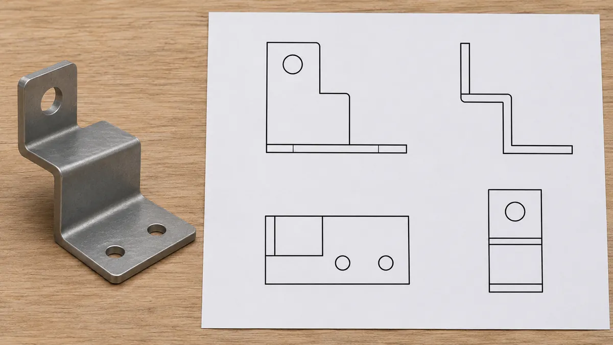
An RFQ drawing package should make the part’s identity and interpretation clear to every recipient. Include the drawing number, revision, sheet number, stated projection convention, named base view and readable projection symbol when applicable. Do not rely on a title block copied from an old project if the current view layout or part has changed.
Add a current isometric view or approved CAD model when it helps show the physical side of an asymmetric feature. Label the reference image or file with the same part and revision. A perspective view is explanatory; it should not silently replace dimensioned requirements. If the drawing and model disagree, identify the discrepancy and ask the responsible designer to resolve it before requesting a firm price or approving a sample.
For a concise handoff, provide:
- part number, title, revision and sheet identifier;
- a clear projection note and named base/front view;
- one asymmetric reference feature tied to a named face or viewing direction;
- a current isometric view or model for visualization, if available;
- the intended mating part or installation direction when relevant;
- separate left-hand/right-hand part identifiers for true mirror variants;
- a contact responsible for answering drawing questions; and
- a record of which approved files apply to the RFQ and sample.
Do not infer that a supplier can reconstruct missing design intent from a product photo. A photograph may be mirrored, rotated, cropped or taken from an unclear side. If a physical sample is supplied, mark its orientation and identify whether it is a visual reference, a fit reference or a complete approval sample. Those purposes are not interchangeable.
How Should Ambiguity Be Resolved Before Sampling?
Pause only the interpretation that is unclear and send a specific question to the drawing owner. Avoid sending a vague message such as “please confirm drawing.” Point to the sheet, view and asymmetric feature: “Please confirm the projection convention and whether hole A is on the mounting-plate side shown in the isometric reference.” Attach a marked-up image only if it is legible and tied to the correct revision.
The designer should return an explicit correction or confirmation. If the view placement itself is wrong, revise the drawing. If the drawing is correct but the symbol or note is unclear, add the missing identification. If the image and model are inconsistent, choose and document the authoritative design intent. Do not permit the factory to change the part orientation in an email reply while the controlled drawing still says something different.
Before a sample is released, record which revision was used, which physical-side feature was checked and who approved the interpretation. A sample review can confirm that the produced sample matches the stated orientation; it cannot repair an ambiguous design requirement by itself. If the intended orientation changes after review, issue a new revision and assess which dimensions, tooling, fixtures, welding access, finishing or packaging checks need to be repeated. The affected checks depend on the change and the product.
| Situation | Appropriate response | Avoid |
|---|---|---|
| Projection note is missing | Ask the issuer to state the convention and revise the controlled file | Guessing from nationality, units or supplier habit |
| Views appear inconsistent | Mark the exact feature and request a corrected drawing or explicit decision | Choosing one view as authoritative without agreement |
| Isometric and orthographic views differ | Confirm design intent and identify the controlling revision | Treating a rendering as automatic approval |
| Part may be a mirror SKU | Assign a distinct item identity and verify the mirrored features | Calling a turned sample a valid opposite-hand part |
| Sample appears reversed | Compare against a named face and current approved files | Approving based on an unlabelled photograph |
What Does a Projection Check Not Replace?
Projection confirmation does not replace dimensioning, tolerance selection, material and finish requirements, revision control, sample acceptance or production inspection. A correctly arranged drawing can still omit a critical dimension or fail to define a mating interface. Conversely, an unusual layout is not necessarily wrong if the convention is clear and the drawing consistently communicates the part.
Do not treat the symbol as evidence that the entire drawing complies with a particular national or international standard. No paid drafting standard is analyzed here, and this buyer guide is not a drafting certification. The cited Autodesk documentation explains software drawing behavior; it does not settle a contract’s document precedence or certify a part.
Use a qualified design owner for technical decisions about geometry, fit and safety. The manufacturer can review whether the information is sufficient to discuss forming, joining, finishing and assembly feasibility within its scope. The buyer’s designer remains responsible for the intended function and approved design inputs. If the intended use has regulated or safety consequences, obtain the relevant qualified review rather than relying on a generic projection checklist.
What Should Buyers Record Before Sample Approval?
Use this short record at drawing review and again when the sample arrives:
- drawing number, revision and sheet;
- named base/front view and stated projection convention;
- one asymmetric feature and its agreed physical side;
- current isometric or model reference, if used;
- named mating face or installation direction;
- left-hand/right-hand variant identifier, if relevant;
- open questions and the person authorized to resolve them;
- sample identity, revision and deviations from production intent; and
- approval date and next action for any correction.
The record should be easy to retrieve alongside the RFQ, BOM and sample photographs. A one-page checklist is often enough for a single part. A multi-SKU program can use a controlled spreadsheet with one row per part and links to the approved drawing. Keep old and current revisions distinguishable so a later quotation does not reuse a superseded view by mistake.
For a China OEM discussion, send a non-confidential drawing and explain the intended product orientation before asking for a sample or manufacturing recommendation. Koitor Hardware is a family-owned custom metal hardware manufacturer that can discuss buyer drawings, samples and practical metal production questions within its confirmed bathroom and home-storage hardware scope. This does not constitute a certified design service or a promise to correct an incomplete engineering definition without buyer approval.
Preguntas frecuentes
Can I tell the projection angle from the buyer’s country?
No. A country or language is not a reliable substitute for the drawing’s own note or symbol. Templates and project conventions can vary, so confirm the issued document with its owner.
Does first-angle projection mean the part itself is reversed?
No. The convention changes where projected views are placed relative to the base view. It does not by itself authorize flipping the part or making a mirror version.
Is an isometric view enough to approve an asymmetric bracket?
It can help show orientation, but a perspective image can hide or distort details. Link it to the same part revision and confirm critical features using the agreed dimensioned drawing or model.
Should the factory choose a convention if the drawing is unclear?
The factory should raise the ambiguity and request clarification. The design owner should resolve intent and update or confirm the controlled file before sample release.
Does a confirmed projection symbol prove the drawing is complete?
No. It addresses view convention only. Dimensions, datums, tolerances, material, finish and revision consistency need their own review.
Clarify Your Drawing Before the OEM Sample
Share a non-confidential drawing, revision and reference orientation to discuss the information needed for a practical metal hardware review.
OEM / MARCA BLANCA
Convierte esta guía de abastecimiento en un resumen del producto
Indícanos el producto que deseas, el tamaño, el acabado, la cantidad del pedido y los requisitos de embalaje. Tu equipo recibirá un análisis práctico de la viabilidad de fabricación antes de recibir el presupuesto.


 English
 Español
 Português
 Français
 Deutsch
 العربية