
Flatness vs straightness is a comparison between different geometric scopes. Flatness controls the form of a specified surface, while straightness controls a line element; in some applications, straightness can also control a derived median line of a cylindrical feature. A check of one line across a part does not, by itself, establish that an entire surface is flat. Buyers should identify the exact feature and control shown on the drawing before comparing inspection results or deciding whether a part meets its requirement.
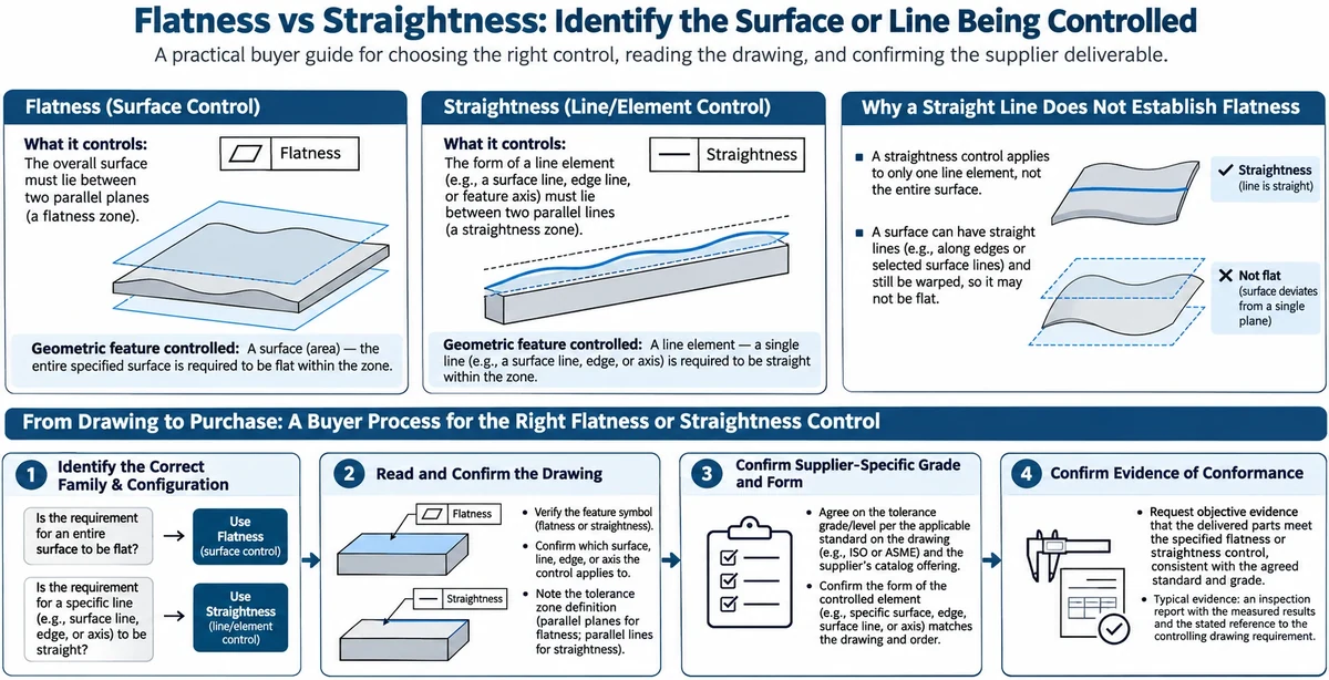
Why does the distinction matter in a drawing review?
A drawing control defines a geometric requirement for a specific feature. If a buyer or supplier reads the wrong feature scope, they may inspect a line when the requirement applies to a surface, or interpret a surface requirement as a single trace. The result can be an inspection record that does not answer the drawing question.
The terms can also appear alongside other controls such as parallelism. Flatness and parallelism are not the same comparison: flatness concerns surface form, while parallelism concerns orientation relative to a datum. This article focuses on the difference between flatness and straightness. A related article may explain flatness versus parallelism or a measurement setup, but those distinct scopes should not be merged into one broad guide.
A hypothetical shelf panel or rail helps illustrate the issue. A buyer might care about the overall surface of a shelf, or about the straightness of a specific edge or line feature. The drawing needs to communicate which one is controlled. This example is conceptual only; it does not create a tolerance, define an inspection method, or claim that a particular instrument is suitable for every part.
What does flatness control?
Flatness is a form control applied to a surface. It limits how far the indicated surface may depart from a perfectly flat condition within the specified tolerance zone. The control addresses the surface as a whole, not merely one selected line on it.
In a drawing review, the buyer should identify the surface that carries the control and understand the feature boundaries. A flatness requirement has no datum reference in its basic form because it controls the form of the surface itself. However, actual interpretation depends on the drawing standard, feature definition, modifiers, and the way the control is presented. This guide does not attempt to reproduce all standard-specific rules or every modifier.
The practical lesson is that a few point readings or one straightedge check may not automatically represent the entire controlled surface. The inspection approach must correspond to the actual feature and applicable drawing requirements. A buyer should ask the quality or engineering reviewer to explain how the reported data address the controlled surface rather than assume that a visual check settles the issue.
What does straightness control?
Straightness controls a line element. Depending on the feature and drawing application, the controlled line may be a line on a surface or a derived median line associated with a cylindrical feature. Those are different contexts and should not be casually combined.
For a surface line, the question is whether the identified line element stays within its specified straightness zone. For a cylindrical feature, a straightness control may apply to the derived median line of the feature, which is constructed from the feature’s actual cross-sections under the applicable standard and drawing interpretation. The buyer should not infer that a straightness symbol always refers to the same kind of line without looking at the controlled feature.
A line can appear straight while other regions of a surface vary. Conversely, a surface may satisfy a surface-form requirement while a particular edge or line feature has its own separate condition. The exact result depends on the geometry and controls applied. A buyer should avoid using one observation as a substitute for another control.
How are flatness and straightness different?
| Comparison point | Flatness | Straightness |
|---|---|---|
| Basic feature scope | A specified surface | A specified line element |
| Drawing question | How does the entire controlled surface depart from flat? | How does the specified line element depart from straight? |
| Typical interpretation | Surface form control | Line-form control, with specialized applications to derived features |
| What one trace establishes | A trace alone may not characterize the whole surface | It may address the identified line, subject to the drawing and method |
| Datum relationship | Basic flatness control does not require a datum | Basic straightness can be applied without a datum; exact application depends on feature and modifier |
| Common buyer error | Treating one line measurement as full-surface evidence | Treating one straight line result as proof that a separate surface is flat |
The table summarizes concepts. It does not state a universal inspection setup or reproduce all requirements from a particular edition of a geometric dimensioning and tolerancing standard. For production acceptance, the drawing and its referenced standard control.
Can one straight line check prove a surface is flat?
Not automatically. A straightness check of one line addresses that line element and does not necessarily describe variation across the full surface. If the drawing requires surface flatness, the inspection record should show how the controlled surface was evaluated under the applicable requirements.
The reverse is also important: a flatness check applies to its specified surface, but it does not necessarily establish the straightness of a separate line feature that has its own control. Each control answers a different question. The buyer should match the inspection result to the feature control frame or drawing note that applies.
A reviewer can use this sequence to avoid a scope mismatch:
- Locate the geometric control and identify the feature it applies to.
- Determine whether that feature is a surface, line element, or a derived feature.
- Read the tolerance and any modifiers according to the drawing’s referenced standard.
- Identify the inspection result and the feature it actually measures.
- Confirm that the measurement method addresses the same feature scope.
- Record unresolved interpretation questions for the responsible engineering or quality reviewer.
If the drawing is ambiguous, the appropriate next step is clarification before acceptance, not an invented tolerance or substitute test. A supplier and buyer may agree on an interpretation, but the controlled drawing should be updated where necessary so that production and inspection use the same requirement.
How should a buyer interpret a measurement report?
A measurement report should identify the feature measured, the drawing requirement, the method or equipment used where required, and the result in a form that can be compared with the specified control. A single value without the feature scope can be difficult to interpret. For example, a report that says “straightness passed” should make clear which line or derived feature was assessed and which drawing requirement was applied.
The report should not be expanded beyond its evidence. A measurement of one edge does not prove the flatness of an entire plate unless the agreed method and applicable standard support that conclusion. A visual inspection can identify visible irregularities, but it may not quantify the geometric control. The buyer should avoid equating “looks flat” with a controlled flatness result.
This is a drawing literacy guide, not a metrology procedure. It does not prescribe instrument choice, point spacing, alignment, fixturing, uncertainty calculation, or acceptance rule. Those details can depend on the feature, size, applicable standard, and agreed inspection plan. When a report and drawing seem to address different features, ask the qualified reviewer to reconcile them before accepting or rejecting the lot.
What should be clarified before requesting a quotation?
An RFQ or drawing review should make the controlled feature understandable to the supplier. If a surface’s flatness matters, identify the surface and the applicable requirement. If a line’s straightness matters, identify the line feature and any relevant application details. Do not add a control simply because it appears in a sample drawing; geometric tolerances can affect manufacturing and inspection effort.
The buyer can prepare a short clarification list:
| Drawing item | Clarification to request | Why it matters |
|---|---|---|
| Controlled feature | Which surface, line, or derived feature is controlled? | Prevents inspection of the wrong geometry |
| Drawing reference | Which revision and standard govern interpretation? | Avoids mixing requirements from different documents |
| Tolerance | What exact value and modifier are specified? | The requirement must come from the controlled drawing |
| Inspection record | What result will be reported and for which feature? | Supports a meaningful acceptance review |
| Responsibility | Who resolves interpretation questions? | Establishes a clear engineering decision path |
| Sample or first article | Which configuration and revision are reviewed? | Keeps the approval aligned with production intent |
The table is a review aid and does not supply missing values. A buyer should not infer a tolerance, modifier, or measurement plan from the product category alone.
What mistakes should buyers avoid?
Treating straightness and flatness as synonyms
One concerns a line element and the other a surface. Similar everyday language does not make the controls interchangeable.
Measuring a line and reporting a surface result
If a requirement applies to a surface, the inspection result needs to address that surface. A selected line trace alone is not automatically full-surface evidence.
Ignoring the drawing’s referenced standard
The control symbol and modifiers should be interpreted in the context of the governing drawing standard and revision. This article does not establish a current normative edition or replace qualified review.
Assuming every straightness control applies to the same feature
Straightness may refer to a surface line or a derived feature depending on the drawing. Confirm what is controlled before interpreting the result.
Confusing form with orientation
Flatness is not parallelism. Parallelism uses a datum relationship and controls orientation; flatness controls surface form. Keep the distinct comparisons on their appropriate drawing interpretation.
Inventing inspection settings
No universal instrument, alignment recipe, uncertainty allowance, or point spacing is established here. Use the agreed inspection plan and qualified review for the actual feature.
How can an OEM factory support drawing communication?
Koitor Hardware is a family-owned custom metal hardware factory focused on bathroom and home storage products. In a confirmed OEM project, buyers can share drawings or physical samples and identify the surfaces or line features that matter to fit, appearance, or assembly. Direct communication can help flag a drawing question for clarification before a quotation or sample review proceeds.
This does not make Koitor an accredited metrology laboratory or a provider of geometric design certification. The company’s approved scope includes custom metal hardware production and communication about drawings, samples, inspection requirements, finish, and packaging within confirmed capabilities. A specialist measurement plan, instrument capability, certification, or tolerance decision must be verified for the actual project and responsible provider.
When a geometric control affects acceptance, the buyer should provide the drawing revision and ask the responsible engineering or quality contact to identify the controlled feature and evidence expected. For product context, see custom bathroom hardware manufacturing and share the relevant drawing through the contact page.
Buyer checklist before reviewing flatness or straightness
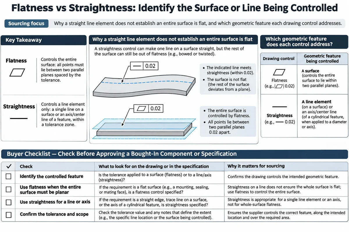
- Identify whether the control applies to a surface, line element, or derived feature.
- Confirm the drawing revision and governing standard.
- Read the actual tolerance and modifiers from the controlled drawing.
- Match the inspection report to the feature the drawing controls.
- Ask what the reported result establishes and what it does not establish.
- Do not treat one straight line trace as automatic proof of full-surface flatness.
- Do not equate flatness with parallelism or other orientation controls.
- Clarify ambiguity with the responsible engineering or quality reviewer.
- Avoid inventing tolerance values or measurement settings.
- Record approved interpretations and drawing changes before production acceptance.
How should teams resolve disagreement about feature scope?
If a supplier and buyer interpret a control differently, first compare the same drawing revision and point to the feature identified by the control. Record whether each party believes the requirement applies to a surface, a line element, or a derived feature, and ask the responsible engineering contact to resolve the interpretation. Avoid choosing whichever reading produces a more convenient acceptance result.
The resolution should be captured in a drawing clarification, approved inspection plan, or other controlled project record. If the geometry or control is unclear, update the drawing before routine production so manufacturing and inspection teams work from the same instruction. A verbal explanation may help a discussion, but a controlled record reduces the chance that later shifts or suppliers use different assumptions.
When the parties agree on the intended feature, they can separately confirm the measurement evidence expected. The feature interpretation and the measurement procedure are related but not identical decisions: settling which geometry is controlled does not automatically select an instrument or sampling approach. Those method details should be reviewed by qualified personnel under the applicable requirements.
What should an inspection plan record?
An inspection plan should connect the drawing feature to the evidence that will be reported. Depending on the project and governing requirements, the record may identify the drawing and revision, the controlled surface or line, the inspection method, the measured result, and the equipment or reference used. The plan should be written by the qualified party responsible for the measurement and reviewed by the buyer when acceptance depends on it. This article does not prescribe which fields are mandatory for every part.
For a surface flatness requirement, the plan needs to address the controlled surface rather than assume that a single edge or selected line represents it. For a straightness requirement, the record should state which line element or derived feature was evaluated. If a component has separate controls on multiple features, the results should remain distinct so one result is not incorrectly presented as evidence for another.
The report should also make clear whether it is a sample review, first-article record, or a later production inspection. These records answer different questions about the product and process. A first sample can reveal whether the drawing and inspection approach are understood; it does not by itself prove every later production item has the same result. Any sampling plan or acceptance rule must come from the project agreement or applicable quality process, not from a generic explanation of geometric controls.
If the reported value is close to an acceptance boundary, the responsible reviewer may need to consider measurement uncertainty and the agreed decision rule. No universal uncertainty allowance or pass/fail adjustment is set here. The parties should define how borderline results are handled in the inspection plan before a dispute occurs, particularly when measurement capability or feature access affects the result.
For recurring orders, retain the approved interpretation with the part revision and communicate it to both production and inspection staff. If the drawing changes, recheck whether the controlled feature or reporting expectation changed before carrying forward the earlier inspection record. This keeps the acceptance evidence tied to the current requirement rather than an outdated explanation.
The review record can also name the responsible engineering contact and the date the interpretation was confirmed. If a later revision changes the feature or control, the earlier decision should be checked again rather than copied automatically.
Record the governing drawing and inspection-plan revisions together so both parties evaluate the same controlled feature clearly.
How should a geometric control reach the inspection report?
A useful measurement record connects the drawing symbol to the actual feature inspected. Identify whether the control applies to an entire surface, a line on a surface, an edge, or an axis, and record the drawing revision and the tolerance zone defined by the applicable specification. If the controlled feature is not obvious from the view, the buyer should clarify its boundary and any datum relationship before inspection. A numeric value without its feature and reference is not enough to reproduce the decision.
The inspection method should also suit the controlled geometry. A straightedge or a few point readings might provide limited observations, but they do not automatically evaluate every point on a surface. Similarly, a surface check cannot be substituted for a line or axis control when that is what the drawing specifies. Fixture support, part orientation, contact points, instrument, environmental conditions, and data reduction can affect what a report means. The method and sampling plan should follow the drawing, agreed quality requirements, and capability of the responsible inspection process.
For flatness vs straightness, ask the supplier to show which feature is controlled and how the reported result was obtained. If buyer and supplier reports disagree, compare feature identification, drawing revision, method, setup, measurement locations, and decision rule before concluding that the part is nonconforming. A report can then state the measured result, method, sample identity, and the requirement used for the decision. This communication framework does not impose a universal instrument-to-tolerance ratio or guarantee that a particular measurement setup is suitable. Flatness vs straightness is a scope distinction, so the report should identify the complete controlled surface or the specific line or axis before presenting a result.
Flatness vs straightness should be resolved by identifying the controlled feature before selecting a measurement approach.
GD&T Basics on straightness and flatness provide additional terminology references; the drawing controls the project requirement.
Frequently asked questions
Does one straight surface trace prove flatness?
Not automatically. A straightness check of a line does not by itself characterize an entire controlled surface. The inspection method must address the drawing’s flatness requirement.
Can straightness apply to a derived line?
In some applications, yes. Straightness can apply to a derived median line of a cylindrical feature. The drawing and applicable standard determine the interpretation.
Is flatness the same as parallelism?
No. Flatness is a form control for a surface; parallelism controls orientation relative to a datum. They answer different drawing questions.
Does this article define how to inspect a part?
No. It explains feature scope and does not prescribe an instrument, alignment approach, sampling pattern, tolerance, or certification.
Can a supplier report “straightness passed” without identifying the feature?
The report should identify the controlled feature and applicable requirement so the buyer can determine what was actually evaluated. Ask for clarification if the result is ambiguous.
Clarify a Geometric Control on Your Hardware Drawing
Share the drawing or sample to discuss the metal product scope and identify questions that need review by the responsible engineering or quality contact.
OEM / PRIVATE LABEL
Turn this sourcing guide into a product brief
Share your target product, size, finish, order quantity and packaging requirements. Your team receives a practical manufacturability review before quotation.

 English
 Español
 Português
 Français
 Deutsch
 العربية