
The types of welding symbols on a drawing help a buyer and supplier communicate what joint is required, where it belongs, which side or sides are involved, and what dimensions or supplementary instructions apply. A complete callout is more than a small weld-type mark. It may include a reference line and arrow, a basic weld symbol, dimensions, finish or contour information, and other notes governed by the drawing’s standard and revision.
For bathroom and home-storage hardware, a buyer may see weld instructions on a basket, bracket, tube assembly, mounting plate or frame drawing. The symbol can guide fabrication, but it does not by itself prove that the finished joint will meet a strength, appearance or corrosion requirement. The buyer should check the drawing convention, identify critical joints, and agree how the sample and production parts will be reviewed.
Types of welding symbols: start with the full callout
The American Welding Society’s AWS A2.4:2020 standard establishes a method for specifying welding, brazing and nondestructive-examination information through symbols. Its official product page identifies the scope and current listed edition reviewed for this guide. Buyers should use the standard named in the contract or drawing, not assume every supplier interprets a symbol under the same system.
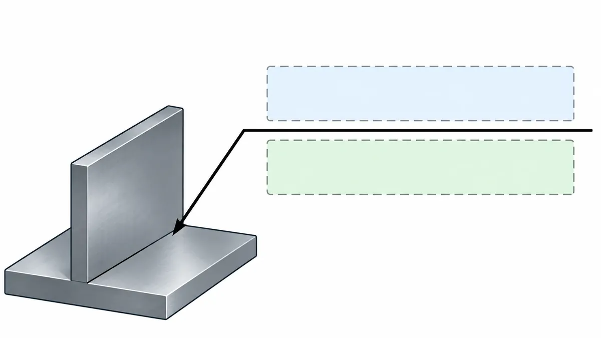
A callout typically combines a line-and-arrow framework with a basic symbol and any needed dimensions or supplementary information. Think of it as a compact instruction package: the line points to the joint or area; the basic symbol communicates the type of weld or operation; dimensions define required size or extent where specified; and additional marks or notes clarify contour, finish, location, process, examination or sequence when the governing convention provides for them.
| Callout element | What the buyer should understand | What to confirm |
|---|---|---|
| Arrow and reference line | Which joint or feature the instruction points toward | Does the arrow clearly identify the intended seam or component interface? |
| Basic weld symbol | The specified weld type or joint-related operation under the cited convention | Does the supplier and drawing use the same symbol standard and edition? |
| Symbol placement | Which side or sides of the joint are intended under the governing standard | Is the joint orientation and side assignment clear in the view? |
| Dimensões | Size, length, pitch, spacing or other defined quantity where shown | Are units, tolerances and datum references stated? |
| Supplementary information | Additional contour, finish, field, all-around, process or examination details if used | Are the marks supported by a legend, standard or note? |
| Tail or general note | Reference to a procedure, process, specification or other drawing instruction | Is the named document available and at the correct revision? |
This table deliberately describes information categories instead of reproducing a full standard chart. A buyer should consult the cited standard and the organization’s drafting practice before interpreting a production-critical symbol. When the drawing is unclear, ask for clarification instead of guessing from a similar-looking graphic.
Basic weld symbol families
Welding standards include basic symbols for different weld types and joint conditions. Common categories encountered on product drawings include fillet, groove, plug, slot, spot, seam, stud and surfacing-related symbols, among others. The exact set, graphic, placement and meaning should be verified against the applicable standard. A symbol name in a buyer’s email is not a substitute for the controlled drawing callout.
Fillet welds
Fillet welds are commonly used where components meet at an angle, such as a bracket attached to a plate or members forming a corner. On a drawing, a fillet symbol can be accompanied by a size, length, spacing or other instructions. For a hardware product, the buyer should identify which joints are structural, which are primarily locating or assembly joints, and which faces are cosmetic. The symbol alone does not decide those acceptance priorities.
Groove welds
Groove welds involve prepared edges or a joint arrangement where the weld is placed within a groove formed between members. Drawings may specify the groove form, preparation, root details, dimensions or backing information. A small sheet-metal or wire-hardware assembly may not use a groove weld at all; the buyer should not add a more complex joint type unless the design and application justify it.
Plug and slot welds
Plug and slot welds join overlapping members through an opening or elongated slot in one part. They can be relevant when two surfaces overlap and access to a continuous edge is limited. A drawing should show the opening, dimensions, number or spacing as applicable, and its relationship to the mating part. Buyers should check whether the hole or slot affects appearance, drainage, fit, coating coverage or assembly.
Spot and seam welds
Spot and seam welds are used in processes that create localized or continuous joining along overlapping sheet components. A callout may include size, spacing, length or other variables. The buyer should confirm the intended process, access, fixture and visible surface requirements with the manufacturing engineer. A spot-weld symbol is not a generic permission to place a weld wherever convenient.
Stud and other specialized symbols
Stud-welding, surfacing, brazing and other operations may use their own symbols or supplementary information under the standard. These should be interpreted in the drawing’s full context. If a fastener, insert or attachment is supplied by another party, the buyer should also identify who provides it and whether the operation is performed before or after coating or assembly.
How placement and supplementary marks change meaning
The location of a basic symbol relative to a reference line, arrow and any additional marks can change the instruction. Under common AWS conventions, placement indicates the arrow side or other side of a joint, but the applicable standard and drawing view govern. A drawing can also identify both sides, an all-around condition, field work, a contour, or an examination instruction. Do not rely on memory for a production decision when the symbol is ambiguous.
Supplementary symbols and notes can convey information that the basic weld type does not. A contour indication may describe the desired profile, while a finish designation can specify how that contour is obtained. A field-weld mark can indicate work performed at the installation site rather than in the factory. An all-around indication can refer to a joint extending around a feature. The standard and project documents define the exact symbol and its interpretation.
For buyers, the key questions are practical: where is the joint, which side must be welded, what length or extent is required, what appearance matters, and when is the operation performed? If a surface will be visible after installation, specify the cosmetic face and define acceptable spatter, undercut, distortion, discoloration or post-weld finishing expectations as appropriate. If weld locations influence a powder-coated or plated finish, review the process sequence and corrosion-related concerns with the responsible technical party.
Do not use a weld symbol to imply an inspection method unless the drawing or applicable standard states it. Nondestructive examination symbols and related instructions may be present in the same standard family, but the weld symbol alone does not establish a test plan, acceptance criteria or a passing result. Specify those separately when the project requires them.
Dimensions and the detail that gets missed
Dimensions turn a general symbol into a more specific requirement. Depending on the weld type and standard, a callout may specify size, length, pitch, contour, groove preparation, root opening, depth or another variable. The buyer must identify the units and references. A value without a unit, tolerance or unambiguous location can produce different interpretations between teams.
For intermittent welds, distinguish the length of each weld segment from the spacing or pitch between segments. The drawing should make clear how many segments are required and where the first and last segments begin. For a basket or frame, an ambiguous pattern can affect rigidity, appearance, drainage, coating coverage or assembly. Use a drawing view or detail to show the pattern where the standard symbol alone is not sufficient for the intended geometry.
The drawing should also identify whether dimensions apply to the finished part, pre-coating condition or a specific datum. A weld can distort a part, and a later finish may change dimensions or clearances. If holes, mating parts or mounting brackets have tight relationships, consider those effects in the drawing and inspection plan. The buyer should not add an unsupported tolerance after the supplier has quoted a different interpretation.
Where the standard refers to a general note or procedure, attach or identify the controlled document. If the reference is missing, obsolete or not shared with the supplier, the callout may be impossible to execute consistently. Record the document owner and revision with the drawing package.
From buyer drawing to a manufacturable instruction
A symbol communicates a requirement only if the supplier can map it to the actual part. For each critical welded joint, provide enough views to identify the components and access, mark cosmetic surfaces, state material and thickness, and call out the applicable standard. If the product is made from wire, tube and sheet, clarify which members meet and whether welds are continuous, intermittent, localized or only required at specified attachment points.
During design review, ask the supplier whether the joint is accessible for the proposed process and fixture. A weld placed close to a bend, hole, edge or highly visible surface may create manufacturing, fit or finishing constraints. The supplier may propose a different weld location or geometry. Treat the proposal as an engineering change: compare function, appearance, assembly, process capability and price before approving it.
For custom hardware, the buyer may need to separate three acceptance questions:
- Joint location and construction: Is the weld in the required position, with the specified type and extent?
- Product function: Does the assembly meet agreed fit, alignment, rigidity or other functional criteria?
- Appearance and finish: Are visible seams, spatter, discoloration and post-weld finish within agreed limits?
The applicable acceptance method should match the product risk. Visual examination may be appropriate for some cosmetic conditions, while other requirements may need a defined measurement, sample plan or qualified test. Avoid a vague instruction such as “strong weld” without specifying the function, geometry, evidence and acceptance authority.
Sample review and production control
Use a representative sample that follows the planned material, joint, process, finish and assembly sequence. Mark the sample with the drawing revision and weld-process assumptions. If the approved sample has a hidden weld or a visible clean-up step, the production instruction should preserve that expectation. A flat weld coupon may help review a process attribute but may not represent the complete product’s geometry or cosmetic face.
Document the important checks. Depending on the project, these may include joint position, count, visible condition, dimensions, alignment, fit with mating parts or performance under an agreed evaluation. Do not assume that a standard weld symbol automatically defines a pass/fail inspection checklist. The buyer and supplier should agree what is checked, by whom, at what stage, with what records and what happens when an issue appears.
Control changes between sample and production. A different drawing revision, material thickness, fixture, joint sequence, welding process, operator plan or post-weld finishing step can affect the result. The buyer should define which changes need notice or approval. For recurring orders, retain the approved sample or clear reference photos and identify the authorized revision. This helps the supplier compare a later batch with the approved baseline.
If a defect is found, record its location, part number, drawing revision, quantity affected and observed condition. Avoid diagnosing a root cause from appearance alone. The supplier’s process engineer or quality owner can investigate the relevant setup and evidence. A buyer should separate immediate containment from disposition and corrective action, and keep any concession or deviation linked to the affected lot.
Common mistakes when reading welding symbols
Looking only at the basic mark
The basic symbol may identify a weld type, but the complete instruction may also depend on placement, dimensions, supplementary marks, notes, tail references and the drawing’s standard. Read the whole callout and its view.
Assuming the standard without checking
AWS, ISO and other systems can differ in conventions and details. A buyer should identify the governing standard and revision on the drawing or contract. Do not mix symbol meanings from different standards.
Treating a symbol as proof of weld quality
A drawing instruction communicates design intent; it does not prove the process was followed or that the finished joint passed inspection. Production records and agreed checks provide separate evidence.
Omitting the cosmetic requirement
The symbol may define construction while leaving the visible finish expectation open. Identify which surfaces matter and agree whether weld dressing, grinding or other post-processing is allowed or required.
Copying symbols without a controlled drawing
An image pasted into an email can lose scale, context, line placement or revision control. Use the released drawing and reference the exact detail when asking a question.
A buyer checklist for a weld callout

Make the review practical
A drawing review works best when the buyer separates three questions that are often collapsed into one. First, what joint is the design asking for? Second, what fabrication method and sequence can produce it while preserving the product geometry and visible surfaces? Third, what evidence will show that the agreed instruction was followed? The symbol helps answer the first question within its governing convention. Process discussion and inspection planning answer the next two, and they may need notes beyond the symbol itself.
For a small welded assembly, a joint can be easy to reach on a flat sample but awkward after other components are installed. A basket frame may be square before welding and pull out of shape as heat is introduced. A mounting plate may conceal a joint that should be inspected before assembly. A polished face may need protection from spatter and handling. These are not reasons to silently reinterpret the drawing. They are reasons to review access, fixturing, sequence and acceptance criteria before approving a production sample.
The buyer can mark critical-to-function or critical-to-appearance joints in a review copy, provided the marking process is controlled and incorporated into the released revision. This helps a supplier distinguish a joint whose location affects fit from one whose bead profile is primarily cosmetic. If a flush or blended appearance is expected, define the visible face and acceptable finish separately. If a joint will be hidden after assembly, decide whether inspection occurs before concealment and what record is retained.
When a symbol appears incomplete, make the clarification specific: identify the drawing view and joint, quote the ambiguous mark, state the unresolved decision, and ask who owns the answer. A useful response should identify the governing standard and revision, provide a marked-up detail or revised drawing, and explain whether the change affects sample approval, tooling, inspection or cost. Keep that exchange with the released file so a later production team does not rely on an informal interpretation that never became part of the controlled specification.
Finally, compare the approved sample against the same controlled drawing and review plan that will govern production. A sample can reveal whether the symbol was understood and whether the joint is accessible, but it does not automatically establish repeatability at order quantity. Identify which features are checked on the sample, which are checked during production, and what happens if a deviation appears. This gives the callout a practical role in sourcing without treating the drawing mark as a substitute for engineering judgment or quality evidence.
Before RFQ release or sample approval, confirm:
- The drawing states the governing welding-symbol standard and edition.
- The arrow points clearly to the intended joint in the correct view.
- The weld type and side or sides are unambiguous.
- Size, length, spacing, count and units are complete where needed.
- Supplementary symbols and abbreviations are defined by the standard or a note.
- The tail references a document that is available and current.
- Material, thickness, finish and cosmetic faces are stated.
- The supplier confirms process access, sequence and any fixture assumption.
- Inspection, acceptance criteria and required records are separately defined.
- Sample approval and engineering-change controls identify the current revision.
If the supplier and buyer interpret a callout differently, resolve it in a revised drawing or written technical clarification before production. A comment in a chat may help identify the issue, but it should not replace a controlled revision when the clarification changes the product requirement.
Perguntas frequentes
What are the main types of welding symbols?
The symbol set depends on the governing standard. Common categories include fillet, groove, plug, slot, spot, seam, stud and other specialized welding or examination symbols. Confirm each symbol in the standard named by the drawing.
What does the arrow on a welding symbol identify?
It points to the joint or area associated with the instruction. The exact relationship between the arrow, reference line and weld side is governed by the selected standard and drawing convention.
Do welding symbols define inspection acceptance?
Not automatically. A symbol may specify examination information where the standard and callout provide it, but the project must still identify the method, extent, acceptance criteria and responsible party as applicable.
Are AWS and ISO welding symbols interchangeable?
Do not assume they are. The buyer and supplier should use the same governing system or document an agreed conversion. If the drawing does not identify the convention, request clarification.
Does a weld symbol prove the part is strong enough?
No. The symbol communicates an instruction; it does not prove design adequacy, process conformance or test performance. Those require engineering review and project-specific evidence.
Sources and scope
- American Welding Society: A2.4:2020 Standard Symbols for Welding, Brazing, and Nondestructive Examination — official standard description and scope. Use the full standard for normative interpretation.
- AWS A2.4:2020 preview — official preview identifying the 2020 edition and its general purpose.
This article summarizes buyer-review concepts and does not reproduce a complete symbol chart or replace the purchased standard, engineering drawing, welding procedure or qualified technical review. It does not claim Koitor uses a particular process or has a specific welding certification or test capability.
Trabalhe com a Koitor Hardware
Clarify the joint before requesting a custom quote
Share the released drawing, material and thickness, visible faces, expected quantity, finish, sample requirement and inspection expectations. Koitor Hardware is a family-owned custom metal hardware factory focused on bathroom and home-storage products. The team can review a confirmed product brief for an OEM manufacturing discussion; design adequacy, symbol interpretation and acceptance criteria should be confirmed by the responsible buyer and engineering parties.
Review a Custom Hardware Drawing
Share the current drawing, joint details, material, finish, quantity and sample expectations so open welding questions can be identified before quoting.
OEM / MARCA PRÓPRIA
Transforme este guia de fornecimento num resumo do produto
Indique o produto pretendido, as dimensões, o acabamento, a quantidade a encomendar e os requisitos de embalagem. A sua equipa receberá uma análise prática da viabilidade de fabrico antes da apresentação do orçamento.


 English
 Español
 Português
 Français
 Deutsch
 العربية