
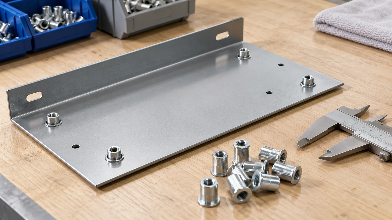
Self clinching fastener minimum edge distance sheet requirements should come from the selected fastener manufacturer’s data for the exact series and host material—not from a generic number copied into a drawing. The buyer must identify the fastener, sheet material and thickness, hole, flange edge, nearby bends or features, and installation method, then confirm the recommended edge distance and sample evidence with the supplier. Too little material around a clinch feature can make installation or retention unreliable, but the applicable limit varies by fastener design and the sheet condition. This article does not prescribe a universal dimension or claim that Koitor installs a particular purchased fastener in a specific product.
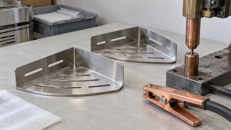
The topic is relevant to thin shelf flanges, mounting plates, and other metal hardware where a threaded attachment may be specified. The key sourcing distinction is edge breakout geometry: it is different from host-sheet hardness or a later push-out/torque-out test. Those other questions may also matter, but they do not replace the drawing-level decision about where the hole sits relative to the part edge and how the selected insert is installed.
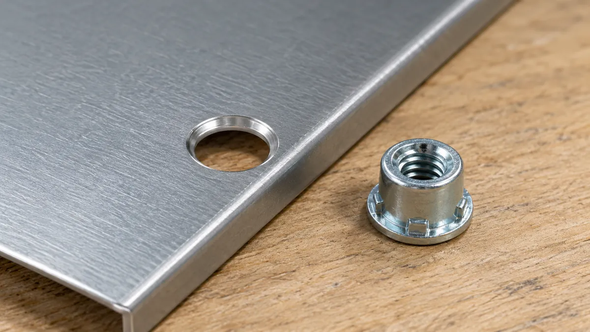
Why does edge distance matter for a clinch fastener in a thin flange?
Edge distance is the relationship between the fastener’s installation feature and the nearby free edge of the host sheet. For a self-clinching fastener, installation depends on the sheet material flowing or forming into the fastener’s designed retention features under the specified press-in conditions. If the hole is too close to an edge, the surrounding sheet can be constrained by insufficient material or can deform toward the edge. The precise failure mechanism and allowable geometry depend on fastener design, material, thickness, hole preparation, and installation conditions.
For a shelf flange, the edge may also be close to a bend, a return, another hole, or a formed wall. The drawing must therefore make clear which edge and which feature are being controlled. A nominal center-to-edge measurement alone can be ambiguous if the hole diameter, edge profile, bend location, or fastener orientation changes. Buyers should use the fastener manufacturer’s definition of minimum edge distance and the product drawing’s datum scheme, then confirm that the flange can be manufactured and inspected accordingly.
Do not assume that a fastener that physically fits through a hole is acceptable. Hole size and position, material thickness, hardness or condition, and press installation are separate inputs. A part may look intact after installation while still being outside the fastener maker’s requirements. Conversely, a generic minimum copied from another insert series may reject a design that the selected product supports—or approve one that it does not. The exact series data and current installation guidance govern.
Which drawing and supplier inputs must be fixed before quoting?
Give the supplier enough information to identify the actual fastener and its surrounding sheet condition. A drawing note that says “clinch nut” without a manufacturer, series, thread, material, finish, or approved equivalent can leave the key geometry unresolved. If an alternate supplier or equivalent component is allowed, define how equivalence is approved and how any different installation footprint affects the flange.
The buyer’s RFQ or controlled drawing should state, as applicable:
- Fastener part number, series, thread, material/finish, and approved substitution rules.
- Host-sheet material and thickness, including any required condition or property limits from the design owner.
- Hole diameter, preparation, location, and the datum scheme for the flange.
- The edge-distance definition and the specific free edge to which it applies.
- Nearby bends, slots, adjacent holes, welds, or other features that may constrain installation.
- Installation side, direction, access, and required sequence relative to forming or coating.
- Sample stage and acceptance evidence, including whether the part is raw, formed, coated, or assembled.
Do not add material-grade or hardness values unless they are supported by the design specification and selected fastener documentation. This guide is not an engineering approval for a particular sheet grade or thickness. If information is missing, ask the fastener supplier and responsible design authority to resolve it before tooling or sample release. Koitor can discuss manufacturing and sourcing inputs within confirmed capabilities, but cannot substitute a generic article for project-specific engineering approval.
How should buyers compare candidate edge-distance guidance?
Compare the actual fastener series and host-sheet combination, not two isolated numbers without context. Self clinching fastener minimum edge distance sheet guidance must be interpreted using the source’s own dimension definition. One manufacturer’s guide may use a distance from the hole center; another document may define the distance from the hole edge or reference a different fastener geometry. Those values are not directly interchangeable unless the definitions, installation conditions, and component family match. Record the source document revision and the basis for the dimension on the drawing or approval record.
| Review item | What to compare | Evidence to request | Buyer risk if unclear |
|---|---|---|---|
| Fastener family | Exact series, thread, geometry, and approved alternate | Current manufacturer datasheet and installation guidance | A limit from a different insert may be applied to the design |
| Edge-distance definition | Center-to-edge, hole-edge-to-edge, or manufacturer-specific reference | Dimensioned sketch or drawing callout tied to the selected document | Supplier and buyer may measure different features |
| Host sheet | Specified material, thickness, and relevant condition | Material record and part revision; additional properties only if required | Recommendation may not apply to the actual flange |
| Nearby geometry | Bends, returns, slots, welds, and adjacent holes | Controlled drawing and representative formed sample | Installation access or edge support may differ from a flat test coupon |
| Installation route | Press direction, access, tooling and operation sequence | Process description and first-article sample identification | A geometrically acceptable layout may be difficult to assemble consistently |
| Acceptance evidence | Visual, dimensional, assembly, or retention checks as required | Agreed inspection plan and sample record | A fastener can be accepted without verifying the feature that matters |
The comparison is a decision framework, not permission to average values from different suppliers. If the chosen fastener maker provides a minimum edge distance for an exact series and sheet condition, use that document as the starting reference. If the component geometry departs from the stated conditions, obtain written technical guidance or qualify the design through an agreed engineering process. Do not treat a product catalog illustration as an acceptance specification.
What should the first article demonstrate?
The first article should represent the intended flange, not just a flat coupon with a convenient hole. Identify its drawing revision, fastener source and series, sheet material/thickness, hole preparation, formed geometry, and installation method. Where coating or assembly follows installation, note the relevant sequence and inspect the condition that the purchase documents define. These records let the buyer connect a result to the product actually being sourced.
Inspection should begin with the controlled drawing dimensions: hole location, distance to the identified edge, and nearby features that could affect the installation. The method must suit the geometry and the tolerance. A caliper photograph may help identify a sample but is not necessarily adequate evidence for a tight positional requirement. Agree the measurement setup and report fields in advance, especially when the edge is angled, rounded, or formed after piercing.
Then verify installation and assembly requirements that the design owner has specified. Depending on the product risk, a project may require a visual check, confirmation of seating, a mating-part trial, or separate retention testing. These checks answer different questions. A successful assembly trial does not prove every dimensional requirement; a retention test does not establish that the specified minimum edge distance was followed. Avoid adding destructive or performance testing unless the project plan calls for it.
Keep the sample reference and evidence together. A useful report identifies the sample, revision, fastener, measurement location, method, and result. If a supplier proposes an alternate component, identify it separately rather than attaching its results to the original part number. Approval should state exactly which configuration and route it covers.
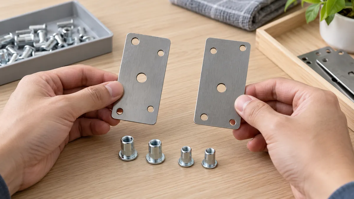
How do bends and secondary features change the review?
A flange is rarely an isolated rectangle after forming. A nearby bend, return, cutout, weld, or second fastener can affect access, support, or how a part sits during installation. The manufacturer’s standard edge-distance guidance may assume a particular flat host surface and installation condition. The buyer should check whether the actual formed feature matches those assumptions rather than translating a two-dimensional dimension blindly.
For a bent shelf flange, identify whether the distance is measured before or after forming and how the hole’s position relates to the final edge. If a hole is pierced before bending, the process can alter the final relationship depending on geometry and sequence. If it is pierced after bending, access and locating may be different. These are process questions to confirm with the supplier; they do not imply that either sequence is automatically better.
The drawing should identify functional edges and datums in a way that supports repeatable inspection. If a formed surface is the assembly reference, the supplier and buyer should agree how the flange is constrained and measured. A dimension from a raw blank may not be equivalent to a dimension from the finished formed part if the drawing does not explain the relationship. Resolve the acceptance condition before the sample review, not after a disagreement.
What changes should trigger renewed approval?
Review the design or sample when a change can affect the selected fastener or the material around it. Relevant changes may include a different fastener series or source, hole size or position, sheet material or thickness, flange geometry, forming sequence, installation tooling, or operation order. Coating or finishing changes may also matter if they affect hole condition, access, or the intended finished assembly. These are review triggers to assess, not proof that every change creates a defect.
The buyer’s change-control plan should define notification and approval responsibility. An alternate fastener should not be treated as equivalent solely because it shares the same thread. Confirm the installation footprint, host-sheet conditions, edge guidance, and any drawing consequences with the relevant technical owner. If a supplier changes the fastener after sample approval, link the new component and evidence to a revised approval record.
Where the original drawing lacks a clear edge-distance requirement, record the clarification as an approved revision or controlled deviation. Do not let an informal email or verbal dimension become a permanent untracked standard. Repeat orders should identify which drawing, fastener, and approved sample condition govern manufacture.
What belongs in the RFQ and inspection checklist?
Buyers can use the following checklist to make the decision actionable. A self clinching fastener minimum edge distance sheet note should point to a particular component and guidance revision, not rely on an untraceable supplier convention:
- Name the fastener manufacturer/series or define the approved equivalent process.
- Identify the host material and thickness from the controlled product specification.
- Mark the hole, datum, and exact edge used for the distance requirement.
- Cite the applicable fastener guidance and keep its dimension definition intact.
- Show nearby bends, returns, cutouts, welds, and other installation constraints.
- State installation side, direction, sequence, and sample condition.
- Agree the first-article measurement setup and evidence record before sampling.
- Define whether separate seating, assembly, or retention checks are required.
- List changes that require buyer notification and renewed approval.
This list is not a substitute for the manufacturer’s fastener data or the design authority’s decision. It makes the information exchange explicit so the supplier can surface a conflict before committing to a sample or production order. If the fastener supplier’s recommendation cannot be met in the current geometry, revise the design or select another qualified arrangement through controlled review.
What should buyers not infer from an edge-distance check?
Meeting a stated edge distance does not by itself prove that the insert is correctly installed or that the assembly satisfies every functional requirement. It only addresses the defined geometric condition under the referenced guidance. Hole quality, host material, thickness, installation process, and other requirements may require separate controls. A clean-looking flange is not proof of hidden retention performance.
Likewise, a push-out or torque-out result addresses a different question from edge distance and should not be treated as a replacement for it. The buyer should avoid combining unrelated tests into one acceptance statement. Define each required property, sample condition, method, and acceptance authority separately. No universal numeric edge requirement can be supplied without the exact fastener and sheet configuration.
Frequently asked questions
Is there one minimum edge distance for all self-clinching nuts?
No. The relevant value and its definition depend on the fastener series, host material and thickness, and installation conditions. Use current manufacturer data for the selected product and confirm deviations with the appropriate technical owner.
Can I use the same distance for a flat panel and a bent shelf flange?
Not automatically. The bent geometry may affect access, support, measurement, or the assumptions behind published guidance. Have the supplier confirm applicability for the actual flange and sample condition.
Does passing a pull-out test prove the edge distance is correct?
No. A retention test and a drawing dimension answer different questions. Use the project’s test plan for retention and separately verify the controlled hole-to-edge geometry where required.
Should the edge distance be measured before or after forming?
Follow the controlled drawing and define the finished feature that matters to assembly. If the dimension is specified on the blank but the final flange is functional, make sure the drawing communicates how the blank dimension relates to the finished part.
What if the selected fastener datasheet does not cover the exact sheet condition?
Do not invent a value. Ask the fastener manufacturer or responsible design engineer for applicable guidance, document the answer, and agree whether a representative sample or additional qualification is required.
Discuss a metal-hardware sourcing question with Koitor
Share the drawing revision, flange material and thickness, selected fastener information, and the evidence your team needs before sample approval. Koitor can review the manufacturing and sourcing inputs within confirmed capabilities and identify when fastener-maker or design-engineer guidance is needed.
Clarify the flange and fastener specification
Send the part geometry, fastener reference, and sample-acceptance questions for a focused sourcing discussion.
OEM / PRIVATE LABEL
Turn this sourcing guide into a product brief
Share your target product, size, finish, order quantity and packaging requirements. Your team receives a practical manufacturability review before quotation.
 English
  Español
  Português
  Français
  Deutsch
  العربية