
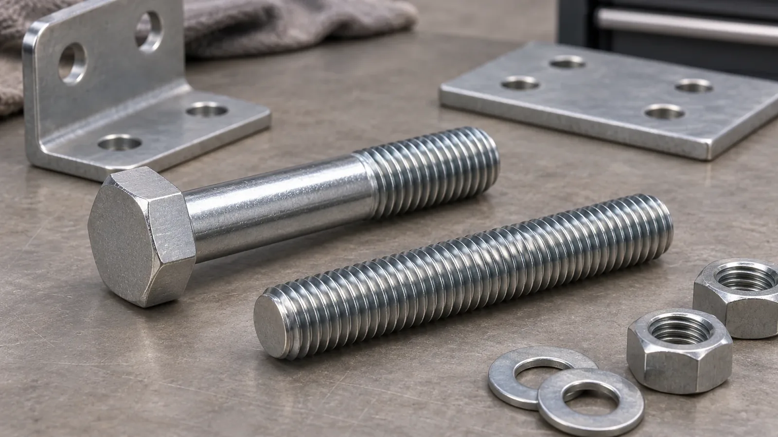
Bolt vs stud is a comparison between two externally threaded fastener arrangements, not a universal contest over which one is stronger. A conventional bolt has a head and a threaded portion that engages a mating component or nut. A threaded stud is headless and may engage a tapped component, accept one or more nuts, or use another arrangement defined by the drawing. Buyers should compare the complete joint, including mating threads, access, assembly order and future removal needs.
For a bathroom or home-storage hardware assembly, a fastener may attach a bracket, mounting plate, rail, frame or accessory component. The choice affects more than the visible fastener shape. It can change how the part is installed, what tool can reach the joint, how the joint is retained and how a component can later be removed. The drawing and approved specification should define the actual mating parts and requirements; a catalog label alone does not.
Bolt vs stud: identify the complete arrangement
A conventional bolt includes a head that bears against one side of an assembly and an externally threaded shank that mates with a nut or a tapped feature. The head can provide a drive interface and a bearing surface, although its shape and drive type vary. The joint may be assembled by placing the bolt through one or more components and engaging the threaded mating part. The actual design determines the sequence and bearing surfaces.
A stud is a headless externally threaded fastener. Depending on its form and the joint, it can screw into a tapped component while a nut secures another component, or it can be engaged by nuts at more than one end. Some studs are threaded along their length; others have distinct threaded ends or an unthreaded portion. A supplier’s catalog terminology can vary, so the drawing and product specification should define the required geometry rather than assuming every supplier uses a label identically.
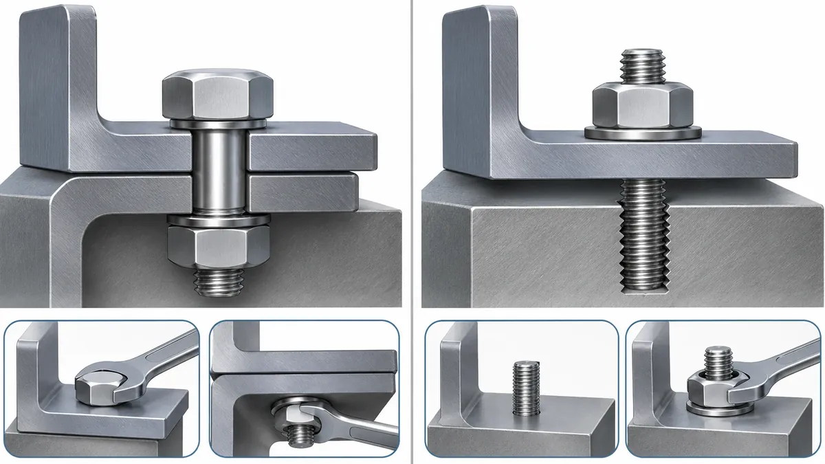
The important comparison is the mating architecture. With a bolt, the buyer should identify where the head bears, how the shank passes through the stack, which element receives the thread and whether there is space to insert and turn the fastener. With a stud, identify the component into which it is installed, how the other part is located over it, how the retaining nut is accessed and whether removal should leave the stud in place. Both arrangements require a defined joint, not merely a part name.
| Comparison point | Headed bolt arrangement | Threaded stud arrangement |
|---|---|---|
| Head | Has a head that can provide a bearing and drive feature | No head; end geometry and threaded regions depend on design |
| Typical mating path | Passes through a component and engages a nut or tapped feature | May engage a tapped base and a nut, or another specified arrangement |
| Installation access | Requires access to the head drive and the mating side as the design dictates | Requires access to the stud installation interface and the retaining nut or mating feature |
| Removal question | Is there access to hold or turn the head and loosen the mating element? | Should the nut come off while the stud remains installed, or should the stud also be removable? |
| Drawing needs | Head form, drive, thread, length, bearing position and mating feature | Overall length, threaded sections, end form, mating engagement and nut arrangement |
| Main buyer risk | Assuming a visible head automatically means convenient service access | Assuming a headless fastener is interchangeable without checking its engaged base and assembly sequence |
These are comparison prompts, not a substitute for engineering design. Thread class, size, material, finish, engagement, torque, preload and other joint details must come from the project’s responsible design authority. Do not infer a strength ranking from “bolt” or “stud” alone.
Map the interfaces before selecting a fastener
Start by drawing or identifying every interface in the joint. Which component has a clearance hole? Which part contains a tapped hole? Does a nut bear against a bracket, spacer or panel? Is there a washer, insert, standoff or separate mounting plate? What surface is visible after assembly? A fastener is only one element in this load path and assembly stack. If the stack is unclear, a supplier may quote a fastener that cannot be assembled or serviced as intended.
For a bolt, check the head envelope and tool approach. A low-profile head may fit under a cover but require a specific drive tool. A larger head may bear differently or interfere with a neighboring part. The drawing should show whether the head is exposed or hidden, which side it faces and whether the fastener is accessible after the product is mounted. If installation occurs in a narrow recess, state that constraint instead of assuming a standard tool will fit.
For a stud, check how it is anchored and what the mating component does as it slides over the stud. Is the stud installed first and then the bracket positioned? Can the bracket be removed without backing the stud out? Does the receiving part have a defined tapped thread or insert? Is there enough protrusion for the specified nut arrangement? Each question depends on the product design and should be resolved in the drawing or approved assembly instruction.
The assembly order can be decisive. A threaded stud may simplify placement of a component over fixed locating points, but a surrounding housing might prevent a nut from being tightened. A bolt may be easy to insert before a cover is fitted, yet impossible to access after assembly. These are conditional geometry examples, not promises that either fastener type is inherently easier. Mock up the sequence using the actual component stack and tools, especially when multiple parts, finishes or decorative covers are involved.
Consider whether a fastener is serviceable. A product that might need repair or replacement can have different access needs from a permanently assembled subcomponent. Define which part should be removable and whether the fastener itself should remain in place. Repeated disassembly, thread condition and replacement part availability are project questions; do not claim that a stud can always be reused or that a bolt is always easier to replace.
Check drawing and procurement information
A quote request should identify the fastener by controlled specification, drawing callout or an agreed reference. Include nominal size and thread specification where engineered; length and measurement convention; head form and drive for a bolt; overall length and threaded-end configuration for a stud; material and finish; quantity; applicable standard or drawing revision; mating component; and any packaging or identification requirement. If a supplier is expected to propose the fastener, label the proposal as subject to design approval.
Do not copy a fastener name from a catalog without matching its interfaces. A catalog may sort a product under a local naming convention that differs from the buyer’s drawings. A long fully threaded stock item, a double-ended stud and a custom shoulder stud may appear in adjacent catalog categories but serve different designs. The exact geometry and use must be confirmed from the technical description and drawing, not inferred from the category label.
If a bolt and stud are both being quoted as alternatives, require each proposal to show the mating part changes, hole or thread assumptions, assembly sequence, tool access and any new components. A price comparison that includes one fastener but excludes a nut, insert, tapping operation or installation labor is not equivalent. Ask the supplier to identify what is included and what still requires customer engineering approval.
For a metal hardware project, also clarify visible finish, corrosion environment and whether the fastener is exposed to moisture or cleaning. The buyer should not assume that matching color means matching base material or corrosion behavior. If a finish affects fit or assembly, record the interface and review a representative sample. Material selection and coating suitability belong to the approved specification and applicable project evidence.
| RFQ or drawing field | What to state or ask | Why the field matters |
|---|---|---|
| Fastener identity | Bolt, stud or a supplier-proposed alternative | Prevents an informal name from hiding a different joint architecture |
| Mating parts | Through-hole, tapped base, nut, insert, spacer and stack order | Shows how the fastener actually engages and retains the assembly |
| Geometry | Thread size/type, length convention, head or end form and protrusion | Makes the proposed part comparable to the drawing and available space |
| Access | Tool direction, clearance, installation side and post-assembly access | Reveals whether a planned sequence can be performed on the product |
| Material and finish | Use the project-approved specification and identify visible surfaces | Helps avoid an unapproved substitution or appearance mismatch |
| Service intent | State which component should be removable and how the joint is accessed | Clarifies maintenance expectations without promising unlimited reuse |
| Evidence and approval | Identify drawing revision, sample and responsible approver | Connects the purchase to the controlled design decision |
The buyer can make the decision reviewable without calculating the joint independently. If a fastener is structurally significant, the design authority should determine the required engineering parameters and acceptance basis. A procurement comparison should not invent torque, engagement or load values or treat a generic chart as a product-specific approval.
Evaluate assembly sequence and service access
Create a simple sequence map before the design is frozen. List the order in which components are positioned, fasteners are inserted, tools are used, nuts are tightened, covers are installed and the finished assembly is inspected. Mark each step that requires access from a particular side. This often exposes a conflict earlier than a rendered product image, because a visual model may show the final form without showing whether a tool can reach the joint.
For a bolt, the assembly plan should state whether the head or nut is held while the other side is turned, if that matters to the design. The bolt vs stud comparison is incomplete until the installer can reach the specified interface in the actual product. For a stud, determine whether it is installed into its base before other components arrive and whether its exposed thread can be protected during handling. These are prompts for the engineering and production teams to resolve; they are not general instructions for tightening a joint.
A useful review record can be a marked-up assembly drawing plus a short sequence note. Number the major components, indicate which face is accessible during installation, show the fastener direction, and identify any cover that is added later. Then ask the assembler to perform the sequence with the proposed components and tools. This is a feasibility check, not a substitute for load design or a qualified fastening procedure. If access is blocked, revise the design or sequence before the released production drawing is frozen.
Fastener comparison should also account for how the joint is inspected. A bolt head can remain visible after installation, while a nut or stud end may be concealed; the relevant inspection point depends on which interface controls the requirement. Decide whether inspection happens before a cover is fitted, whether a record is needed and how the approved assembly is identified. Avoid writing a generic “check fasteners” instruction when the drawing can identify the exact location and acceptance owner.
If the product has a decorative cover, identify whether it conceals the fastener or prevents future access. If removal is expected, determine which part is removed first and whether the fastener remains captured. If removal is not part of normal service, document that instead of allowing a later installer to assume the joint is intended for repeated disassembly. Service requirements belong to the product’s use case and design responsibility.
When reviewing the assembly, keep the parts oriented as they appear in the product drawing. A fastener can appear to fit in a loose sample but become inaccessible when the frame, wall plate or trim is positioned. Use a visual or physical mock-up to record the insertion direction, accessible face and any parts that must be installed first. If the joint cannot be observed after final assembly, decide what in-process check or record demonstrates that it was assembled as intended.
Separate cosmetic review from functional approval. A fastener finish may be visible while the thread engagement is hidden; one review does not establish the other. Identify who approves appearance, who approves the design interface and who confirms the production method. A clear responsibility map is particularly useful when a purchased fastener is supplied by one party and installed by another.
Sampling should represent the intended joint and installation sequence. A loose fastener sample shows dimensions and finish but may not prove that the full stack assembles correctly. A representative assembly can reveal conflicts between the head, nut, mating component and tool. Record the sample’s part and drawing revision, note which features were checked and identify any open issues. Approval should be tied to the correct version rather than a photo with no reference.
When a supplier proposes a substitution, compare the entire interface and sequence. Ask whether the new choice changes the mating hole, tapped feature, nut, insert, washer, head clearance, protrusion or access. Request an updated drawing or marked-up view. A change that looks minor in a purchasing line can alter how the product is assembled, inspected or maintained.
Common comparison mistakes
Assuming one type is always stronger
Strength depends on the complete joint design, fastener specification, material, engagement, geometry, installation and applicable loading. The words “bolt” and “stud” do not supply a universal ranking. If capacity is critical, rely on the project’s qualified design and documented evidence.
Comparing only visible profiles
A bolt head and a headless stud look different, but the mating thread and assembly stack determine how each is used. Review the joint drawing and the component that receives the thread. Do not assume a visually similar item is dimensionally or functionally interchangeable.
Ignoring tool access
A fastener may be technically compatible yet impossible to install with the available access after other parts are assembled. Map the tool path and assembly sequence. If access is tight, identify it in the RFQ and validate a representative assembly.
Treating catalog labels as specifications
Supplier catalog categories are useful for finding parts but do not replace thread, length, head/end, material and interface requirements. Confirm the technical details and the supplier’s terminology, especially for stud configurations.
Assuming reuse or easy service
Serviceability depends on the designed access, mating threads, condition and intended maintenance. Neither a bolt nor a stud automatically supports unlimited disassembly. Define which component should be removed and confirm the sequence with the responsible designer.
Buyer checklist before approving a proposal
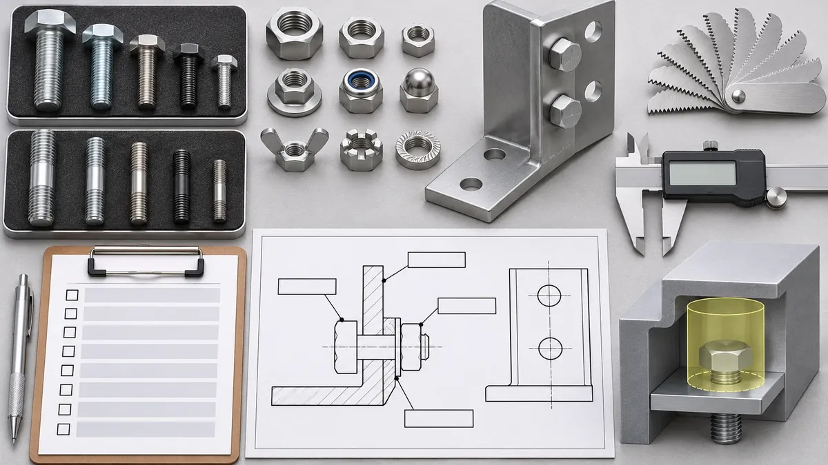
Before approving a bolt, stud or alternative, confirm:
- The controlled drawing identifies the fastener or clearly marks it as a proposed alternative.
- The mating parts and thread engagement arrangement are visible or specified.
- Bolt head/drive or stud end/thread details match the intended interface.
- Length and measurement convention are unambiguous.
- Tool access and installation sequence work in the assembled product.
- Material and finish match the approved project requirement.
- Any nut, insert, washer, tapping or secondary operation is included or excluded clearly.
- Service or removal expectations identify which component should remain in place.
- The sample represents the actual joint stack and drawing revision.
- Structural claims or load requirements are supported by the design authority’s evidence.
Frequently asked questions
What is the main difference between a bolt and a stud?
A conventional bolt has a head and an externally threaded shank. A stud is headless and externally threaded, with its engagement and mating arrangement determined by the drawing. Confirm the exact configuration with the supplier.
Can a stud replace a bolt without changing the product?
Not necessarily. A substitution can change the receiving thread, nut arrangement, hole, installation sequence, access and service behavior. Review the complete joint and obtain design approval before changing the specification.
Are studs always stronger than bolts?
No universal conclusion follows from the labels. Strength depends on the specified fastener and the joint design, materials, engagement and application. Use project-specific engineering evidence rather than a generic comparison.
When might a buyer consider a stud arrangement?
A stud may fit a design where one threaded end engages a base and another component is secured by a nut, or where the specified assembly sequence benefits from a fixed threaded projection. The design must confirm geometry, access and suitability.
What information should a bolt or stud RFQ include?
Identify the controlled part or proposal, thread, length convention, head or end form, material, finish, mating part, access constraints, quantity and drawing revision. State what components and operations are included in the quote.
Does the fastener name establish serviceability?
No. State which component should be removable, how the joint is accessed and whether the fastener is intended to remain installed. Confirm the design’s maintenance sequence.
Sources and scope
- Bolt Depot: Studs, Rod and Stock — catalog examples show headless stud and stock categories, but the supplier’s naming convention is not a universal design rule.
- University of Florida Fastener Reference Guide — supports the basic headed-bolt versus headless-stud distinction and common mating arrangements; project-specific engineering parameters are not reproduced here.
- Scope note: This article focuses on the head, mating threads and assembly access distinction; check the current live internal-link index before referencing any adjacent Koitor guide.
This article does not provide torque values, thread engagement calculations, load ratings, fastening safety advice or a universal strength comparison. The final fastener and joint must be approved against the actual product design and applicable project requirements.
Work With Koitor Hardware
Clarify a fastener interface before a custom quote
Share the current assembly drawing, fastener specification, mating components, material and finish, quantity, sample requirement and access constraints. Koitor Hardware is a family-owned custom metal hardware factory focused on bathroom and home-storage products. The specific fastener arrangement and structural criteria must be confirmed for the project before they are represented in a quote.
Review a Hardware Joint Before Quoting
Share the current drawing, mating parts, finish, quantity and sample expectations so the proposed fastener interface can be clarified.
OEM / PRIVATE LABEL
Turn this sourcing guide into a product brief
Share your target product, size, finish, order quantity and packaging requirements. Your team receives a practical manufacturability review before quotation.


 English
 Español
 Português
 Français
 Deutsch
 العربية