
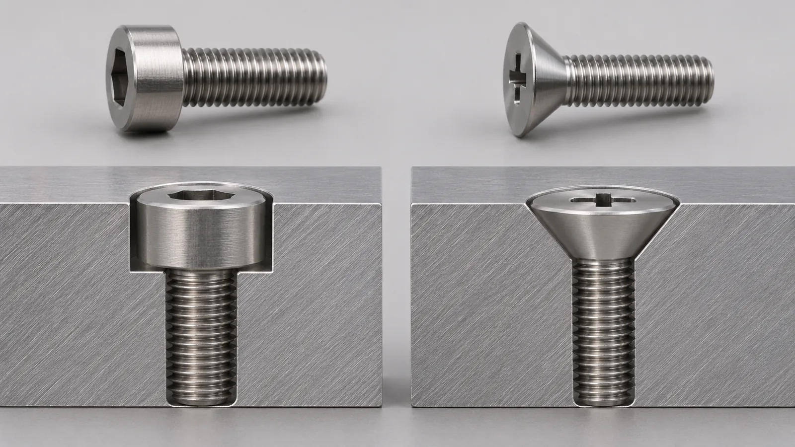
Counterbore vs countersink comes down to the recess geometry and the screw head it is intended to receive. A counterbore is generally a cylindrical, flat-bottom recess; a countersink is a conical recess intended to match a conical head profile. Buyers should specify the hole or recess dimensions, head form, fastener, material thickness, and drawing revision together. The terms alone do not establish strength, centering accuracy, stress behavior, or suitability for a particular product, and a generic table cannot replace the drawing for the actual assembly.
What problem does counterbore vs countersink solve?
The recess allows a fastener head to sit in a defined relationship to a plate, bracket, cover, or other component. A buyer reviewing a drawing may see a callout for a counterbore or countersink and assume the difference is simply visual. But the profile affects the mating head shape, available material around the feature, assembly appearance, and clearance to adjacent components. If the buyer orders a screw independently from the plate, the two parts can fail to fit even though each supplier followed an incomplete instruction.
The comparison is useful during product development, quotation review, and supplier changes. A new supplier may interpret a sketch differently. A drawing may show a flat-head screw while the plate uses a cylindrical recess, or it may describe a countersink without a clear angle or diameter. The buyer needs to identify the intended head and make the geometry unambiguous before approving a sample or release.
This is not an article about choosing a fastener based on a generic load claim. A recess design should come from the responsible engineer or controlled drawing. The article explains the terms and the questions a buyer can raise; it does not assign universal dimensions, angles, tolerances, or strength effects. The exact values depend on the screw head, material, thickness, manufacturing method, finish, and design requirement.
How do counterbores and countersinks differ?
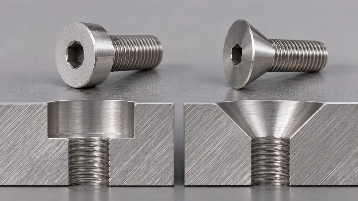
A counterbore is a cylindrical recess with a flat bottom or shoulder. It is commonly paired with a fastener head that has a flat bearing face and cylindrical form, although the actual head and drawing control the fit. The recess provides room for the head to sit below or flush with a surrounding surface when designed accordingly. Its diameter and depth need to be specified for the selected head and assembly.
A countersink is a conical recess. It is commonly intended for a flat-head or countersunk screw whose underside is also conical. The included angle and recess dimensions should match the selected screw head and drawing requirement. If the angle or diameter is wrong, the head may contact only at an edge or remain proud. These are fit observations; they do not by themselves predict joint strength.
Some drawings use “spotface” for a shallow, flat surface preparation around a hole. It should not be casually substituted for a counterbore; the required geometry and function need to be clear. Carr Lane’s counterbore data concerns drill bushings, which is useful for understanding the term but must not be transferred as a universal hardware dimension table. Hubs’ counterbore and countersink comparison similarly explains the basic geometric distinction, while the product drawing remains the authority for the specific part.
| Feature | Counterbore | Countersink |
|---|---|---|
| General profile | Cylindrical recess, flat bottom | Conical recess |
| Typical mating head form | Flat bearing face with cylindrical head | Conical underside, often a flat head |
| Key drawing details | Diameter, depth, location, and related hole | Major diameter, angle, location, and related hole |
| Buyer review | Confirm head clearance and seating | Confirm head angle and flush/proud requirement |
| Limitation | Generic tables do not define the complete joint | A matching appearance does not prove performance |
The table is a terminology aid, not a design prescription. Real fastener standards and drawings can define more precise forms and dimensions. Confirm the relevant standard, screw designation, and tolerance on the controlled drawing instead of relying on a general description.
In a counterbore vs countersink review, it helps to show the screw head profile next to the recess section. The drawing can identify the intended head, bearing surface, and final surface position without asking the supplier to infer those details from a catalog photograph. If the head is decorative or partially concealed by a cap, include that part in the assembly view. A clear illustration reduces interpretation risk, but dimensions and standards remain necessary for controlled production.
In a buyer’s review, the best comparison begins with the intended assembly view and a section through the feature. The section makes it easier to see whether the recess is cylindrical or conical and where the fastener head is expected to contact the component. If the drawing shows only a plan view, ask the designer to add a detail or dimensioned section. A product photograph may show a flush head but usually cannot reveal the recess depth, angle, or contact geometry. The drawing should communicate enough information to quote and inspect the part without relying on a supplier’s interpretation of an image.
Also keep the through-hole or pilot feature distinct from the recess. The central hole and the counterbore or countersink have related geometry but can have separate dimensions and functional requirements. A supplier may need to manufacture them using more than one operation. The buyer should not assume that a recess callout automatically defines the hole size, clearance, thread, or positional relationship. Each controlled feature should be dimensioned or referenced explicitly on the drawing.
How should a buyer specify the recess and fastener together?
Begin with the assembly. Identify the screw type, head form, diameter, length, thread, drive, material, and finish. Identify the plate or component material, thickness, visible faces, and mating parts. State whether the head should be flush, below the surface, or allowed to project, if that is a controlled design requirement. A phrase such as “countersunk hole” is incomplete if the drawing omits the intended angle or screw-head specification.
For a counterbore, the drawing should define the recess diameter and depth along with the pilot or clearance hole as appropriate to the design. For a countersink, define the included angle and major diameter or the governing standard and fastener reference. The exact callout depends on the design; this guide does not supply a single recommended angle or dimension. Avoid copying a drilling table for drill bushings into a sheet-metal bracket or decorative hardware design.
Mark critical location and orientation. A recess that is correctly sized but misplaced can interfere with an edge, bend, weld, or mating part. The supplier should review the feature in relation to material thickness and manufacturing sequence. If a finish is applied, clarify whether it covers the recess and how the finished head will seat. Coating build or surface preparation can affect fit, so a raw-part measurement may not fully represent the finished assembly.
The drawing review should consider the component’s manufacturing route. A recess may be drilled, machined, stamped, formed, or produced through another specified process; the suitable route depends on material, geometry, quantity, and design controls. Do not assume that a supplier will use a particular tool simply because a feature has a familiar name. If tool access, burr direction, cosmetic surface, or repeatability matters, make the requirement visible and ask the supplier to explain the proposed process. Any process proposal still needs to achieve the drawing and acceptance requirements.
Material thickness and distance to edges are design considerations for the responsible engineer. A buyer can flag a very close edge, a bent flange, or a weld near the recess and ask for manufacturability review, but should not set a universal minimum edge distance based on a generic article. A change in recess depth may alter remaining material; a change in head style can alter the contact surface. The design owner should assess structural implications and approve revisions before the supplier makes them.
The supplier may ask whether the drawing controls the sharpness of the edge at the recess, the deburring approach, or the visible transition into the surrounding face. These questions matter for touch surfaces, cosmetic panels, and parts that receive a finish. The buyer should respond through an approved drawing note or sample criterion rather than an informal chat alone. If the part has a consumer-facing appearance, define any visible ring, tool mark, or burr acceptance clearly; if it is concealed, still address assembly and handling safety where applicable.
Specify any inspection method needed for the feature. A visual sample may show whether the screw head appears flush, but it cannot establish all dimensions. If depth, angle, or position is critical, state the measurement datum, method, and acceptance criteria. The supplier can propose a suitable inspection approach for review. Keep the agreed criteria within the project drawing or quality record so that the sample, production checks, and reorder use the same reference.
What should the sample and drawing review check?
Check the actual screw with the actual component. Confirm that the fastener head enters the intended recess and seats as shown by the design. Observe whether the head is proud, flush, or recessed, and whether the contact is consistent around the profile. Do not force a mismatch or adjust a screw at assembly to hide an incorrectly specified feature. Record the sample identities and drawing revision.
Inspect the recess for burrs, rough edges, deformation, and finish buildup where relevant. A sample can reveal visible interference or cosmetic concerns, but its appearance is not a substitute for specified dimensions. If a chamfer or countersink is intended to be visible, define its appearance and edge treatment. If the recess is concealed, still identify any assembly or clearance requirement.
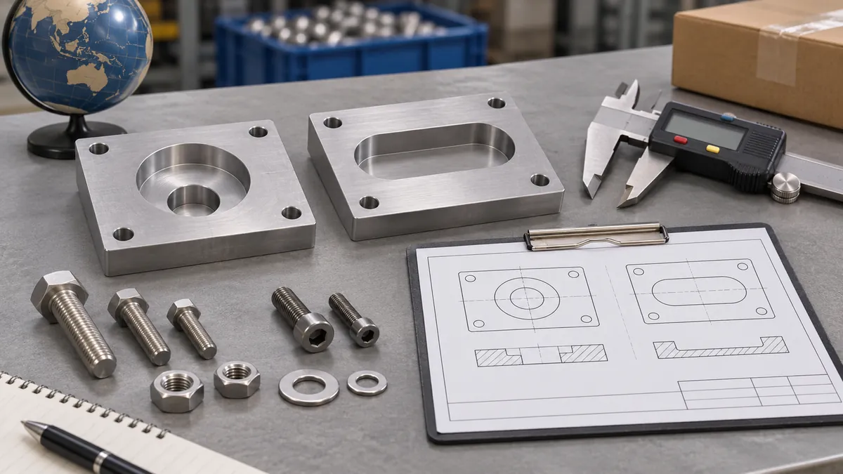
Review nearby features: a bend, weld, flange, slot, or thin edge may limit the material available around the recess. This article does not claim that one recess is universally stronger. The engineer should assess the structure, loading, and geometry. The buyer can ensure that the correct drawing and material are provided, and ask whether the manufacturing route can hold the specified features without changing the design.
When the component is coated or plated, inspect the finished condition with the intended fastener. A recess may accept a bare screw but bind after finishing if the specification does not account for the final interface. The buyer should not invent a coating allowance; ask the supplier and design owner to review the controlled drawing and sample. If a surface is masked, identify that area and verify the mask boundary on the approved sample.
When inspecting the finished assembly, use the fastener and mating part from the approved BOM. A substitute screw can have a different head angle, head height, or shoulder, so a passing fit with an unapproved sample does not validate the production configuration. Check for rocking, uneven gaps, visible damage, and the specified head position using the agreed method. If the part cannot be checked easily after assembly, define the suitable in-process or first-article inspection before production begins.
Record the measurement result with the actual datum and drawing revision. If a feature is inspected with a depth tool or angle gauge, identify the method and any calibration requirement agreed for the project. Avoid treating a visual “looks flush” judgment as a dimensional result where the specification calls for a particular depth or profile. Conversely, do not invent a numeric acceptance limit when the drawing has not defined one; seek clarification from the design owner before approving the inspection plan.
For a sample review, use a short checklist that records which screw was fitted, the head position, visible gaps, finish condition, and any measurement reference. Take photographs from the same orientation for comparison, but use them as supporting evidence only. A photo can help a second reviewer understand the observation, while a dimensioned drawing and a physical sample remain the basis for manufacturing approval. If the sample has been hand-finished or assembled with a nonproduction screw, label those differences so that no one treats it as a fully representative production article.
What mistakes cause recess-fit problems?
Using the terms interchangeably. A cylindrical flat-bottom counterbore and a conical countersink are different geometries. Use the intended term and show the profile clearly.
Specifying the recess without naming the fastener. The recess exists to mate with a head or another defined feature. Include the screw reference or complete head dimensions.
Leaving angle, diameter, or depth open. The supplier may choose a reasonable process default, but that is not necessarily the buyer’s design intent. Mark the required dimensions or reference a controlled standard.
Using a generic table outside its scope. A drill-bushing counterbore table is not a universal design chart for hardware assemblies. Confirm the source, component type, and dimensions before adopting any reference.
Inspecting only the raw part. The finished interface may differ because of coating, burr removal, or assembly sequence. Check the final part with the intended screw where the fit requirement applies.
Assuming flush means correct. A screw can look flush while contacting at an unintended area, or a cosmetic appearance can hide an incorrect feature. Use the drawing and suitable dimensional checks.
Changing head style without revising the recess. A flat-head screw and a cylindrical head require different mating profiles. Treat a substitution as a design change and obtain approval.
Inferring strength from recess type. Neither term alone establishes strength or stress behavior. The responsible engineer evaluates the complete part and joint.
How can an OEM supplier help resolve the drawing?
Provide the supplier with the controlled drawing, screw specification, material, finish, assembly context, and required fit. Ask the supplier to identify ambiguities and confirm the proposed manufacturing method. A supplier can flag a dimension that appears difficult to manufacture or inspect, but any design alteration should be reviewed by the buyer’s engineering owner and approved in writing.
For a custom metal bracket or cover, the recess may interact with forming, stamping, machining, or other processes. The chosen route, available tooling, material thickness, and inspection access affect how the feature is made. The supplier should explain any tradeoff based on the actual part rather than apply a generic rule. If the supplier recommends a change, request a marked drawing and sample that shows the changed geometry before production release.
The RFQ should state whether the supplier supplies the fastener or only the metal part. If the screw is purchased separately, make the interface a shared control point and state who verifies compatibility. A screw drawing and a bracket drawing that live in separate systems can drift apart. Keep both references tied to the same assembly revision and require supplier notification before substituting the head style or dimensions.
For project context, review the custom bathroom hardware manufacturing page oder OEM home-storage hardware page. These do not provide a design certification. Share the component drawing, mating screw, intended appearance, target quantity, and inspection needs to clarify the scope for a quotation.
If the buyer changes the finish after the first sample, repeat the fit review where the recess is part of the visible or functional interface. A raw metal sample and a coated production sample may seat differently. The supplier should identify whether the finishing sequence changes a controlled dimension or requires a mask, but the design owner should decide the permissible condition. Update the approval record and drawings together so that the new finish reference does not become disconnected from the original geometry.
Buyer checklist before approving a counterbore or countersink
Before approving a quotation, compare the supplier’s drawing readback with the buyer’s intended screw and recess. Confirm that the quote names the same geometry, the correct fastener head, and the controlled revision. If the supplier lists a standard or default angle, verify that it matches the design rather than assuming it is acceptable. A written clarification at this point is less costly than discovering an interface mismatch after finishing or assembly.
This counterbore vs countersink check should be repeated whenever a supplier changes the screw head, material thickness, or finishing route.
Keep the approval linked to the purchase order and revision history.
- Identify the correct geometry: cylindrical flat-bottom recess or conical recess.
- Specify the exact fastener head form and complete screw reference.
- Show recess diameter, depth or angle as required by the controlled design.
- Identify the related hole, datum, location, and drawing revision.
- Confirm material thickness and nearby bends, edges, welds, or openings.
- State whether the head must be flush, proud, or recessed if controlled.
- Review the finished interface with the actual screw and part.
- Mark coating, plating, masking, and visible surfaces that affect the recess.
- Agree on inspection method and acceptance criteria for critical dimensions.
- Keep fastener and component drawings linked to the same assembly revision.
- Approve any supplier-proposed geometry or head changes in writing.
- Do not infer strength or performance from the recess label alone.
Häufig gestellte Fragen
Is a counterbore the same as a countersink?
No. A counterbore is generally a cylindrical recess with a flat bottom; a countersink is conical. The drawing should identify the intended profile and mating head.
Which screw head usually fits a countersink?
A countersunk or flat-head screw has a conical underside intended to seat in a matching countersink. Confirm the actual head dimensions and angle from the fastener drawing or applicable standard.
Does a counterbore always make a joint stronger?
No. Strength depends on the full design, materials, dimensions, loading, and other details. The recess label does not establish structural performance.
Can I use a drill-bushing counterbore table for a hardware part?
Do not assume so. A reference may be limited to drill bushings or a specific application. Use the controlled drawing and a source that applies to the component being designed.
Should the screw head sit perfectly flush?
Only when that is the design requirement. State the required head position and inspect the actual finished assembly against the approved drawing and sample.
Review a Recess Detail Before Your Hardware Sample
Share the drawing, intended fastener, material, finish, and target quantity to clarify the manufacturing information for your custom hardware quotation.
OEM / EIGENE MARKE
Verwandeln Sie diesen Beschaffungsleitfaden in ein Produktdossier
Teilen Sie uns Ihr Zielprodukt, die Größe, die Oberflächenausführung, die Bestellmenge und Ihre Verpackungsanforderungen mit. Ihr Team erhält vor der Angebotserstellung eine praxisorientierte Prüfung der Herstellbarkeit.
 English
 Español
 Português
 Français
 Deutsch
 العربية