
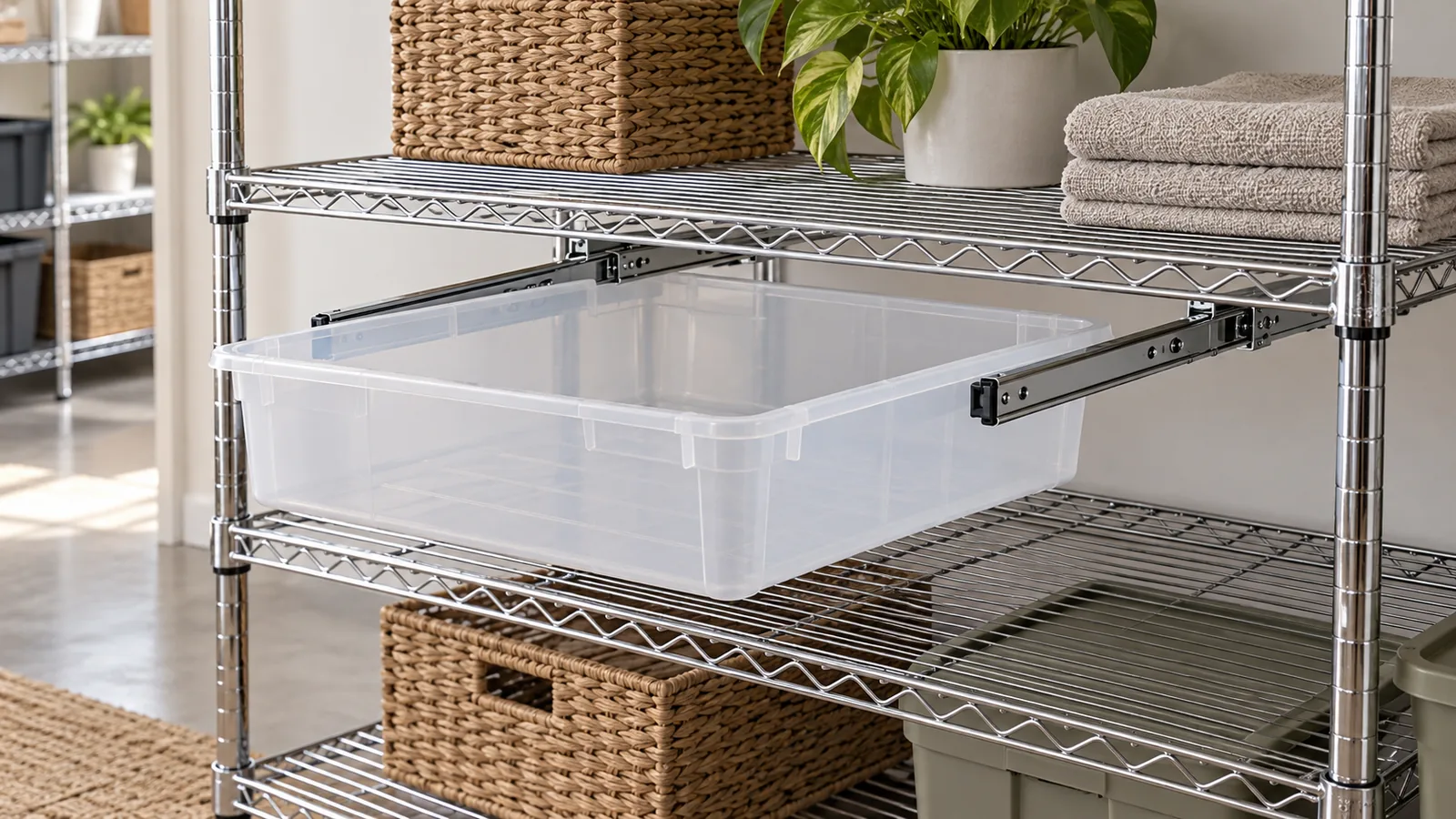
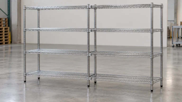
For a modular wire-rack assortment, wire shelf undershelf slide compatibility is a three-part fit decision: the shelf must accept the slide pair, the two slides must match the bin’s rim or support geometry, and the bin must travel without striking adjacent shelves or rack posts. A part that fits the shelf width can still fail as a complete assembly if the bin is too wide, the rails are spaced incorrectly, or the available vertical clearance is insufficient.
Importers and private-label product teams should approve the shelf, slide pair and intended container together—not select each from a catalog dimension in isolation. Ask for controlled drawings, identify the specific adjustment range, and inspect a production-intent sample with the bin loaded only according to supplier instructions. Do not assume a purchased slide or bin is compatible with a generic wire rack, or infer a load limit from a successful fit check.
How does the shelf-slide-bin interface work?
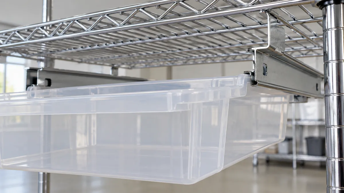
An under-shelf storage assembly has several interfaces that should be named in the RFQ. First, a bracket or attachment connects each slide to the underside of the wire shelf. Second, the left and right slides form a matched pair and establish the working spacing. Third, the bin is supported or guided by a rim, flange or other feature that engages each slide. Depending on the product design, a stop or retention feature may also limit withdrawal. The exact mechanism varies by system; confirm it from the supplier drawing and instruction sheet rather than assuming a familiar-looking rail uses a cabinet-drawer mechanism.
The slide pair must be parallel enough for the bin to enter and travel as intended. If the pair is too close, the bin rim may bind or be compressed. If too far apart, the bin may wobble, drop out of engagement or fail to be retained as designed. A mismatched pair can produce uneven movement even when each individual rail appears straight. The bin’s outside width is not necessarily the correct spacing reference: identify the actual surfaces that touch or ride on the slides.
The upper shelf and lower shelf create a second envelope. Measure usable vertical clearance from the underside of the selected shelf to the next obstruction, then include the bin’s rim, handle, contents, slide hardware and any motion needed for removal. A bin that slides into place empty might be difficult to grasp after loading or could scrape the shelf below. Similarly, a protruding slide bracket can reduce usable space even if the bin itself clears.
Metro’s Super Erecta adjustable undershelf slides listing says its slides can be spaced to fit containers or tote boxes of different widths and presents a shelf-width selection. That is a useful example of an adjustable, named-system accessory—not evidence that its slides fit other shelf brands, arbitrary bins or every wire-shelf geometry. The buyer should obtain the current instructions and drawing for the exact proposed parts.
Which dimensions should buyers specify?
Specify the contact geometry, not just nominal shelf and bin widths. The following dimensions help the supplier identify and check the assembly; use a drawing datum for each measurement so buyer and supplier do not measure different edges.
| Interface | Buyer input to record | Supplier confirmation |
|---|---|---|
| Wire shelf | Overall width and depth, wire layout, edge profile and revision | Intended attachment points and compatible shelf model |
| Slide pair | Overall length, adjustable spacing range, mounting method and finish | Pair orientation, permitted spacing and part numbers |
| Bin | Maximum outside width, rim/flange profile, depth and height | Supported contact surfaces and compatible bin model |
| Travel | Usable extension, insertion direction and stop/retention needs | Actual travel and any system-specific limitations |
| Vertical envelope | Shelf-to-shelf gap and nearby post/accessory clearances | Required clearance and installation sequence |
| Intended use | Stationary or movable rack, access frequency and contents category | Applicable instructions and any documented load guidance |
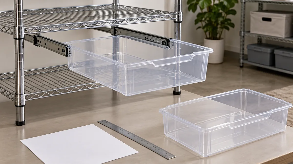
Agree on measurement conditions. Is the container width measured across the widest body, at the rim, or between the surfaces engaging the rails? Is shelf depth measured from the outside edge or the usable wire area? Does slide length include its bracket? Mark the datums on a simple interface drawing or sample sketch. This prevents a common RFQ ambiguity: a buyer gives an outside dimension while the supplier quotes a contact dimension. For wire shelf undershelf slide compatibility, the drawing should identify the working width at the bin’s actual engagement point, not merely repeat the container’s catalog width.
For a private-label program with multiple container sizes, ask the supplier to map each approved bin to a slide-spacing range and shelf model. Do not convert one successful size into a general statement that all containers within a width range are acceptable. Rim shape, taper, stiffness, handle projections and molded tolerances may alter how the bin engages, even when nominal widths are similar. If the buyer expects substitutions, list the approved variants and check each one.
Also identify material and finish only to the degree they affect the interface. A coating on a rail or shelf attachment can change clearance; a plastic rim can flex differently from another container design. The supplier should state which construction and finish the sample represents and whether a material or finishing change triggers a new fit review. Avoid requesting an unsupported universal tolerance: derive acceptance limits from the drawing, intended engagement and repeatable sample results.
How should buyers check insertion, travel and removal?
Review the assembly in its installed orientation. Confirm left and right slides are the intended matched parts, attached at the specified locations and aligned with the shelf. Insert the empty bin using the documented method. It should engage both sides as designed rather than riding on a single rail or being forced into place. Observe whether the bin stays level through its travel and whether any bracket, wire intersection or post interferes.
Then check the end conditions. At full insertion, confirm the bin does not hit a post, wall, adjacent accessory or shelf feature. At the intended withdrawal point, confirm the user can reach the grip area and remove the container as designed. If the slide has a stop or retention feature, test it according to the system instructions; do not assume that a rail will prevent pull-out simply because the sample feels snug. If removal is meant to be tool-free, verify that operation with the production-intent parts and instructions.
Check the assembled rack at relevant shelf heights. A bin below the lowest shelf may have a different clearance problem than one mounted under a high shelf. Record the shelf level, orientation, rack revision and any neighboring accessories. If the rack is on casters or intended to move, do not extend the bin during movement unless the supplier’s instructions expressly allow that use. A static insertion review is not a stability or transport test.
The fit review should cover repeatability. Remove and reinsert the container several times if that reflects expected use and is within the supplier’s instructions. Note rubbing, binding, uneven travel, looseness, rattling, unintended disengagement or visible damage to the finish. This is an observation of the sample under stated conditions, not a prediction of service life. Establish separate tests and acceptance criteria for durability, load or repeated cycling when the product’s risk and documented requirements call for them.
What changes when the bin is loaded?
An empty bin is useful for checking basic geometry, but it does not show how the specified assembly behaves with its intended contents. Define a representative loading condition with the supplier: item type, distribution, orientation and any maximum fill or weight already supported by product documentation. Do not invent a test load or use a generic weight as a substitute for a rated capacity. If the intended load is not documented, treat that as an open specification to resolve before commercial approval.
During a buyer-defined sample check, observe whether both slides remain engaged, the bin stays level and the shelf or rail attachment shows visible movement. Watch the bin rim and contact surfaces while inserting and withdrawing it. Unequal loading can expose a different behavior from a centered load, so describe the condition if testing off-center placement is relevant. The purpose is to compare the sample with agreed requirements; it is not to establish an engineering rating without a defined method, equipment and acceptance criteria.
If the assembly will be marketed with load information, request the system supplier’s applicable documentation and verify what exact combination it covers: shelf model, slide pair, bin, rack configuration and test or rating conditions. A rating for a shelf does not automatically apply to an undershelf slide or container. Likewise, a bin catalog’s capacity does not establish the permissible capacity of the assembled slide interface. Keep these values and their source separate in product records.
Where the bin is removable for washing or replenishment, inspect the parts after the agreed operation. Look for shifted brackets, loosened fasteners, scuffed finishes, cracked or permanently deformed rims, or a change in insertion effort. Report what was observed along with the number of cycles and conditions; avoid phrases such as “tested for long-term use” unless a defined test supports them. If cleaning agents, moisture or temperature matter, specify the exposure conditions separately and seek the materials guidance from the component suppliers.
How should a supplier sample be approved?
Ask for a complete assembly rather than isolated components. A sample pack should identify the wire shelf, both slides, brackets or fasteners, bin and any stop or retention part. Include the part numbers, revision levels, finish and instruction sheet. Confirm that the physical sample represents the proposed production source; a hand-adjusted demonstration sample may not represent the repeatability of the normal assembly process.
Inspect attachment and alignment first. Confirm the slides are installed on the intended underside surfaces, parallel according to the drawing and positioned at the approved spacing. Check that fasteners do not protrude into the bin path and that the attachment does not damage the shelf finish. If there are adjustment slots, record the approved position and range instead of relying on a technician’s undocumented adjustment.
Next, compare the bin engagement and access to the approved sample. Confirm the rim makes contact where intended, that both sides support or guide the container, and that the chosen stop does what the supplier documentation describes. Insert and remove the bin, observe clearance at the neighboring shelves, and photograph the assembly from the side, front and underside. Note any fit issue and keep the actual sample or controlled photos with the buyer approval record.
Separate acceptance questions by function: dimensional fit, ease of insertion, travel, removal, appearance and any specified load or durability requirement. A sample that looks polished can still have a fit problem; a bin that moves smoothly while empty does not prove a rated load. If criteria are not yet established, agree on a measurable observation or ask for technical documentation instead of giving a vague “looks good” approval.
What should the RFQ and change record contain?
The RFQ should describe the system as a coordinated kit. Attach the wire shelf drawing or identified rack model, bin drawing and candidate slide data. State the shelf location, mounting method, intended bin size and the access direction. Ask the supplier to confirm the exact compatible combination and identify which inputs are assumed versus verified. If the slide or bin is buyer-supplied, name the responsible party for compatibility and sample approval. A concise wire shelf undershelf slide compatibility schedule can list each shelf model, slide pair, bin and revision, with separate approval status for every tested combination.
Include packaging and assembly responsibilities. Will the slides arrive installed, separately bagged or bulk packed? Are left and right rails marked or keyed? Does the pack include fasteners, instructions and spare components? If a consumer or downstream assembler installs the kit, review the instructions and part identification with a real sample. Packaging should prevent metal parts from rubbing against a visible finish or deforming a plastic rim in transit; validate the actual packout rather than assuming a carton or bag is sufficient.
Change control should identify which updates require review: shelf wire arrangement, shelf depth, post position, slide model or spacing, bracket, fastener, finish, bin supplier, rim geometry, packaging or instruction revision. An apparently minor substitution can change contact or clearance. Record the approval date, sample configuration, applicable drawings, open limitations and who approved each item. Re-run the fit review when a controlled interface changes.
For a modular assortment, define a compatibility matrix rather than a broad “fits wire shelving” claim. List each supported shelf and bin combination, its slide model, approved orientation and any documented limits. Mark untested combinations as not yet approved. A matrix makes product-page copy, purchase orders and replacement-part decisions more consistent, while preserving the distinction between verified combinations and future options.
Häufig gestellte Fragen
Can any under-shelf slide fit a wire rack?
No. Attachment geometry, shelf depth, slide spacing and bin engagement vary. Confirm a specific rack, slide pair and container combination with drawings and a complete sample.
Is nominal bin width enough to choose the slide spacing?
Usually it is not enough by itself. Identify the bin rim or surfaces that actually engage the rails, and confirm the spacing range with the slide supplier. Outside width can differ from the working contact width.
Does a smooth empty-bin travel test prove the rated load?
No. It checks basic fit and operation under the observed conditions. Any load capacity must come from applicable system documentation or a defined test for the exact assembled configuration.
Should the bin remain attached during rack movement?
Only if the product instructions support that use. Check whether the rack and slide system are designed for movement with the bin installed or extended; do not infer permission from the fact that parts fit together.
Discuss a wire-rack storage component
Share the shelf profile and drawing, intended container, slide data, finish, access needs and sample conditions. Koitor can discuss metal-storage hardware manufacturing and sourcing inputs within confirmed capabilities; purchased slide and bin compatibility must be verified for the exact parts.
OEM / EIGENE MARKE
Verwandeln Sie diesen Beschaffungsleitfaden in ein Produktdossier
Teilen Sie uns Ihr Zielprodukt, die Größe, die Oberflächenausführung, die Bestellmenge und Ihre Verpackungsanforderungen mit. Ihr Team erhält vor der Angebotserstellung eine praxisorientierte Prüfung der Herstellbarkeit.
 English
  Español
  Português
  Français
  Deutsch
  العربية