
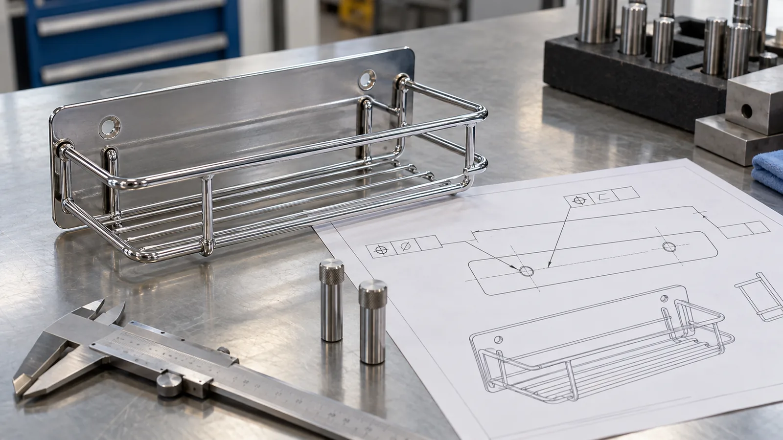
For a bathroom or home-storage rack, position tolerance with maximum material condition can help a buyer describe how a mounting-hole pattern relates to a functional datum while allowing the stated bonus tolerance when the feature departs from its maximum-material boundary. The useful acceptance question is not simply whether two hole-center measurements look close: it is whether the specified feature, datum reference, mating parts, and inspection method together protect assembly fit. Before using a position tolerance maximum material condition bonus on a drawing, the buyer and supplier should confirm the applicable standard, feature type, datum scheme, and production-stage condition. No universal tolerance value can be selected without the product geometry and functional requirement.
Why does the tolerance modifier matter to a hardware buyer?
A formed or welded storage product may connect to a wall plate, another frame, or a set of fasteners. If a hole pattern is displaced from its intended relationship, the buyer may see difficult assembly, forced alignment, visible skew, or a mismatch between mating components. A coordinate distance by itself may not describe the design intent well: it can omit which surface establishes the reference, whether the holes must act as a pattern, and how feature size affects fit.
Geometric dimensioning and tolerancing (GD&T) gives a drawing a way to define the location of a feature relative to datums. When the maximum-material-condition modifier is permitted and applied to the relevant feature control, the tolerance zone may gain additional positional allowance as the actual feature size moves away from its maximum-material condition. For a hole, that condition is associated with the smallest permitted hole size; for an external feature, the material boundary is associated with its largest permitted size. The exact interpretation must follow the drawing standard and the full feature-control callout, not a shorthand label copied into an email.
This matters commercially because a buyer can avoid rejecting a functionally acceptable part for a measurement that does not represent the drawing’s intended assembly boundary. But bonus tolerance is not a blanket relaxation. It cannot fix an incorrect datum reference, guarantee that two parts assemble, or make an undersized hole acceptable. The buyer still needs a functional reason for the callout and a verification plan tied to the mating condition.
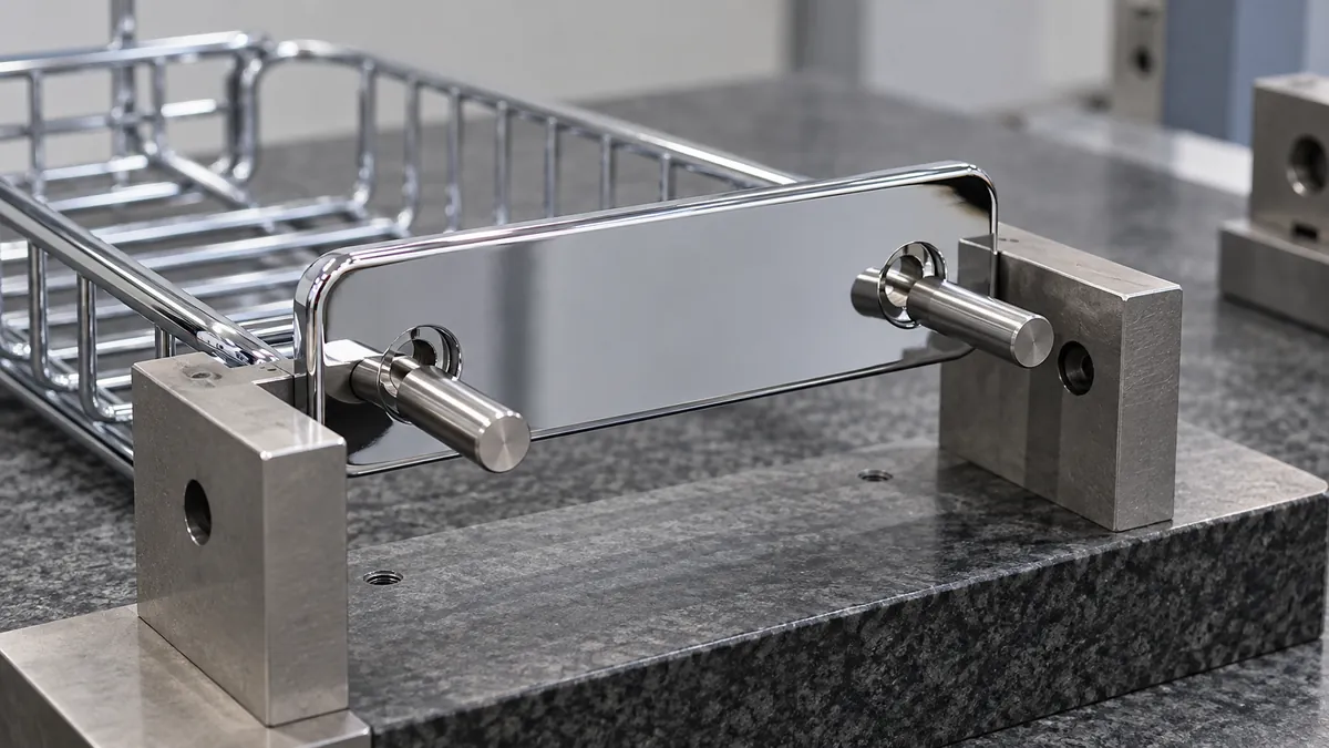
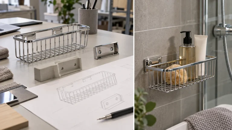
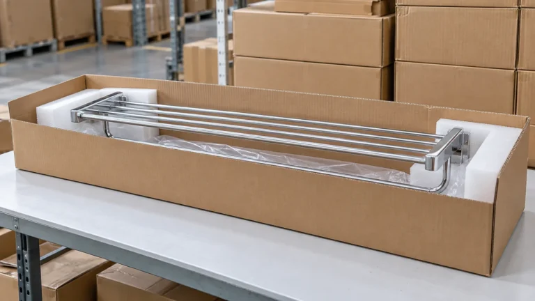
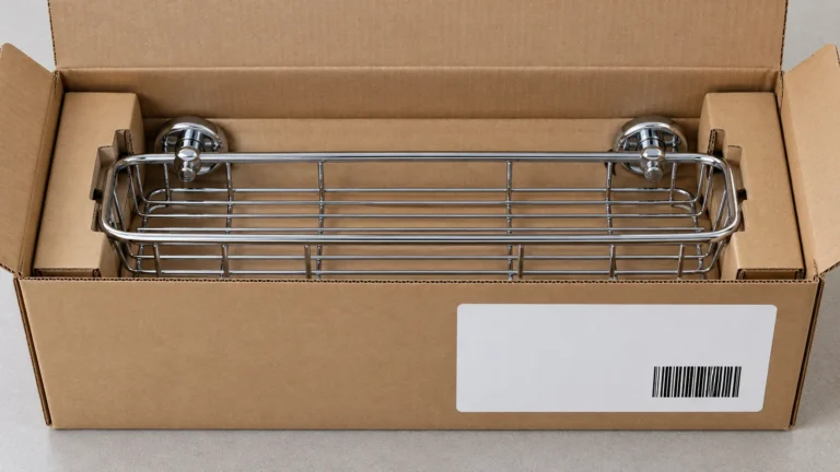
The visual examples in this article are illustrations only. They do not show a Koitor inspection result, a calibrated measurement, or a validated rack design. A project drawing, approved standard, supplier capability discussion, and sample review remain necessary before acceptance criteria are set.
Define the feature and functional datum before selecting a callout
Start with the assembly, not the symbol. Identify the actual interface: perhaps a rack plate fastens to a second plate, a bracket locates against a frame, or a mounting pattern aligns with a buyer-supplied component. Decide which surfaces or features establish the part’s orientation in that assembly. A datum should be physically meaningful and repeatably accessible for both design interpretation and inspection.
For a hole pattern, the drawing should make clear whether the locations are evaluated individually or as a related pattern. It should identify the applicable datum references, any material-condition modifiers, and the feature-size limits. If the hole is in a thin formed bracket, the inspection approach should also account for edge condition, burrs, coating, and whether the measurement applies before or after finishing. These conditions can affect access or the functional size of the interface; they should be agreed rather than assumed.
The buyer should distinguish a datum from a convenient measuring surface. A broad outside edge may be easy to touch with a caliper but may not control how the assembled rack sits. Similarly, a basket rim can appear square in a photograph while its mounting plate is rotated relative to the intended reference. A simple drawing review with the supplier can expose these differences before sample tooling or packaging work is finalized.
Ask the design owner to identify the mating hardware and the assembly sequence. If the product uses separate screws or inserts, confirm which components are included, which are buyer-supplied, and whether the acceptance review uses the production-intent fastener. Do not substitute an arbitrary gauge pin or oversize screw for the specified mating condition without documenting why that check is valid.
| Drawing or sample input | Buyer should clarify | Why it affects acceptance |
|---|---|---|
| Feature identity and size limits | Which hole, slot, stud, or pattern is controlled? | The material boundary and applicable tolerance depend on the feature type. |
| Datum reference frame | Which surfaces or features locate the part in assembly? | A position result is meaningful only relative to the stated references. |
| Mating component | What part or fastener engages the controlled feature? | Assembly fit is a system relationship, not a hole measurement alone. |
| Finish and inspection stage | Is acceptance before or after plating or coating? | The measured condition must match the approved requirement. |
| Drawing revision and method | Which standard and inspection method govern? | Teams need one controlled interpretation and evidence record. |
How should a buyer understand position tolerance maximum material condition bonus?
The concept can be explained without calculating a project value. A feature control defines a positional tolerance at a stated material condition. If the feature’s actual size departs from that material condition in the permitted direction, an additional amount of positional tolerance may be available under the applicable GD&T rules. That additional amount is commonly called bonus tolerance. The feature size still must satisfy its own size limits, and the datum references must still be interpreted as drawn.
For an internal feature such as a mounting hole, the smallest allowed hole is generally its maximum-material condition because that size leaves the most material around the opening. A hole that is larger within its permitted size range can provide more positional tolerance under an MMC callout. This relationship is useful only when the design’s functional boundary and the chosen callout support it. A buyer should not infer that a larger hole is always harmless: fastener clearance, bearing surface, edge distance, appearance, and retention may impose separate limits.
KEYENCE’s GD&T explanation describes the MMC modifier and bonus tolerance as part of positional tolerance interpretation. It is a useful public technical introduction, but the drawing’s governing standard and the project’s actual callout control. For complex datum systems, composite controls, projected tolerance zones, slots, or virtual-condition analysis, the design authority should confirm the calculation and acceptance rule rather than relying on a simplified summary.
Consider a rack plate with a pair of mounting holes and a mating component. If a supplier reports the hole size and center locations separately, that record may not answer whether the feature pattern complies with the position callout. Conversely, a functional check that mates a particular component may reveal fit but may not prove every drawing characteristic. The buyer should define whether acceptance requires measured GD&T evidence, a functional gauge, assembly demonstration, or a combination, and which party owns each record.
The phrase position tolerance maximum material condition bonus should describe a controlled drawing relationship, not a permission to accept any part that can be forced together. If the fastener requires unusual force, the plates bend during assembly, or the finished rack sits visibly out of alignment, investigate the full stack-up and the specified datum setup. Do not attribute the condition to one hole without checking the mating part and inspection method.
Compare measurement evidence with functional assembly evidence
Measurement and assembly checks answer related but different questions. A coordinate measurement or suitable inspection setup can evaluate a specified feature relative to datums. A functional gauge may test whether the part fits a boundary condition. A trial assembly can reveal handling or installation issues. The buyer should not ask one method to prove something outside its scope.
For example, a pin that enters a hole says something about local size or access at that location, depending on the pin and procedure. It does not necessarily establish the true position of the entire pattern. A visual check can show obvious skew but cannot quantify the controlled relationship. A mating-part trial is useful only if the mating component, orientation, fastener, tightening condition, and operator method are representative and repeatable.
| Evidence option | What it can help establish | Limitation to record |
|---|---|---|
| Drawing-based dimensional report | Selected dimensions and feature relationships when the method matches the callout | Report scope, datum setup, instrument and feature accessibility must be reviewed. |
| Functional gauge | Fit against a defined boundary or interface | Gauge design and rule must match the drawing; it may not report actual feature size. |
| Trial assembly | Practical engagement and assembly sequence | One mating sample may hide variation or may not represent all production parts. |
| Visual review | Obvious orientation, damage, burr or finish concerns | Visual appearance does not establish geometric compliance. |
An efficient RFQ can state the controlled features, the reference surface or datum scheme, the measurement stage, the sample quantity or selection rule, and the evidence expected with the first article. It can also ask the supplier to flag any ambiguity before producing a sample. If the supplier proposes a measurement method, review it against the drawing rather than accepting the instrument name as proof by itself.
What should a production-intent sample review include?
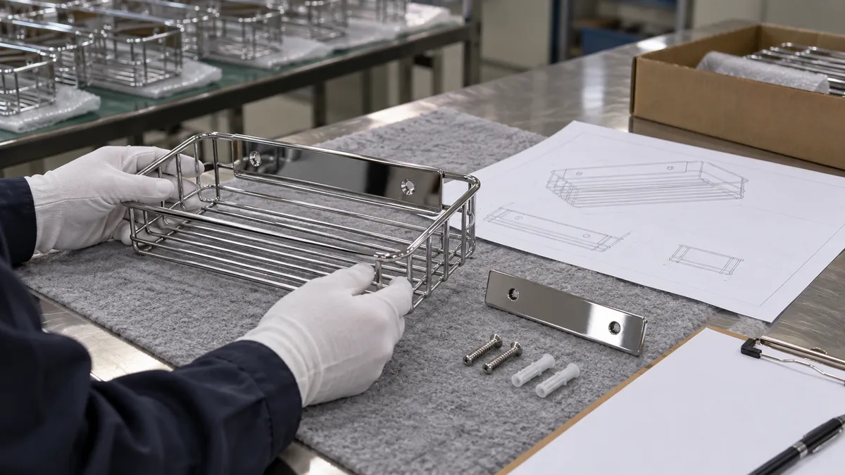
Use the current drawing revision and the actual mating parts wherever possible. Label the sample set so that each piece can be traced to its configuration without confusing it with another revision. Record whether the sample is formed, welded, finished, or fully assembled, and identify the state required by the drawing. If the finish changes the accessible surface or feature size, agree whether the relevant measurement is before or after finishing.
The review should capture both feature evidence and assembly behavior when both matter. A buyer can confirm that the correct fasteners are supplied, that they engage without forced bending, that the rack seats in the intended orientation, and that the paired mounting points work as a system. A measurement record should identify the datum setup and method; a photo should show orientation and sample identity, not serve as a substitute for numeric evidence where a numeric callout is required.
Record any mismatch as an observation first. For example: “the right fastener cannot be started by hand with the mating plate seated” is more useful than “hole position is wrong” before the measurement and root cause are established. The issue could involve position, hole size, burrs, the mating component, finish buildup, or a difference in the assembly setup. A controlled recheck can narrow the cause without prematurely changing the drawing.
When a sample fails, agree on the correction and repeat the same check on the revised sample. Keep the rejected and accepted configuration separate. If a buyer changes the hole spacing, plate thickness, material, finish, or mating fastener, determine which parts of the previous approval remain applicable. A revision record helps purchasing, engineering, and quality avoid treating a visually similar part as the same configuration.
What belongs in the RFQ and supplier acceptance plan?
A clear RFQ turns a GD&T callout into shared evidence expectations. It should provide the released drawing, units, governing standard and edition where applicable, feature-size limits, complete position control, datum references, and the intended mating condition. If the buyer expects an inspection report, identify the required characteristics and the method or method-approval process. Avoid asking for “MMC compliance” without specifying the feature control and the evidence needed to demonstrate it.
The buyer should also identify the approval stage. Early prototypes may support design learning but may not represent production tooling, final finish, or shipment packaging. A production-intent sample can answer more questions, but the parties should record what changed between prototype and sample. For repeat orders, link the order to the approved drawing and product configuration, and define which design or process changes require notification or renewed review.
For metal hardware programs, a supplier discussion can include formed-part location, welding sequence, fixture access, finishing route, and assembly method if they influence the controlled feature. These are topics to evaluate for the specific product; they are not claims that one process guarantees a tolerance. Koitor’s OEM home-storage hardware manufacturing work can begin from a buyer drawing or physical sample, with the acceptance plan agreed for the project rather than inferred from a generic product description.
The parties should keep the specification proportionate. A tolerance that does not protect a product interface can add inspection burden without improving the buyer outcome. A vague tolerance can produce inconsistent interpretations. A useful review asks what can fail at assembly, what feature controls that failure, which datum reproduces the assembly reference, and what evidence both sides can reasonably create and review.
Liste de contrôle pour la validation par l'acheteur
Before releasing the drawing or accepting the first article, confirm:
- The controlled feature and its size limits are identified on the current revision.
- The datum reference frame reflects how the component is located in the actual assembly.
- The full feature control, material-condition modifier, and governing standard are unambiguous.
- The mating fastener or component used for functional review is representative.
- Inspection stage and finish condition are agreed, especially if finishing can affect the interface.
- Measurement evidence and functional assembly evidence are not treated as interchangeable.
- The supplier’s report identifies sample revision, datum setup, method, and scope.
- Any drawing, fixture, finish, or mating-part change triggers a deliberate review of approval status.
Foire aux questions
Does MMC mean a buyer can accept any hole that assembles?
No. The feature must still satisfy its size limits and the complete position callout. A practical assembly check is useful evidence but does not automatically replace drawing-based acceptance. The buyer and design authority should agree how each requirement is verified.
Is bonus tolerance the same as changing the hole-size tolerance?
No. Bonus tolerance concerns the position tolerance available under a specified material-condition modifier as the actual feature size departs from the material condition. The hole-size limits remain a separate requirement.
Can a caliper verify the whole hole pattern?
A caliper may be appropriate for selected dimensions, but the instrument alone does not define a datum setup or prove a GD&T position requirement. The inspection method must be appropriate to the callout and feature geometry.
Should the buyer prescribe the supplier’s inspection machine?
Usually the buyer should specify the feature, acceptance requirement, and required evidence. The supplier can propose a method, and the buyer or design authority can review whether it addresses the drawing. Specialized requirements may call for an agreed method or qualified inspection resource.
What if the supplier’s report and the trial assembly disagree?
First compare the drawing revision, datum setup, sample identity, mating part, finish condition, and assembly procedure. A disagreement can come from different definitions or conditions. Reconcile the evidence before changing a tolerance or accepting a forced fit.
Review a drawing-led hardware specification
Share the relevant drawing, mating interface, and sample-approval question with Koitor so the project team can clarify what manufacturing and acceptance evidence is needed.
Fabrication pour compte de tiers / Marque de distributeur
Transformez ce guide d'approvisionnement en cahier des charges
Indiquez-nous le produit souhaité, ses dimensions, sa finition, la quantité commandée et vos exigences en matière d'emballage. Votre équipe recevra une analyse pratique de la faisabilité de la fabrication avant l'établissement du devis.
 English
  Español
  Português
  Français
  Deutsch
  العربية