
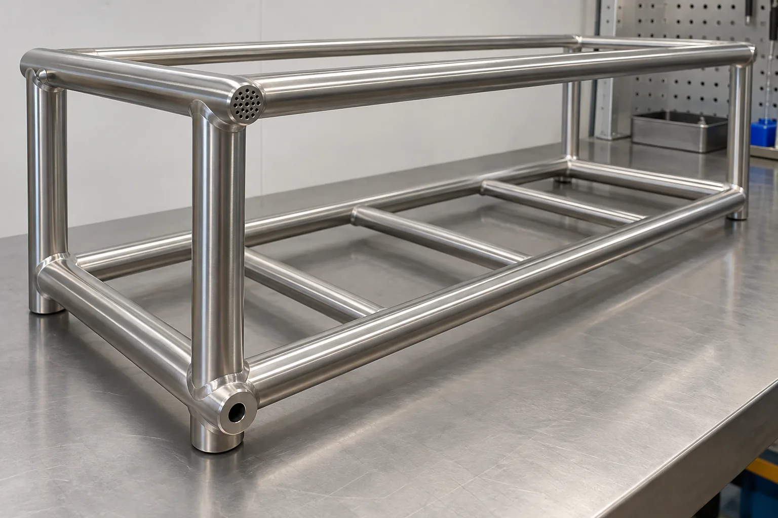
For powder coating vent drain holes on a tubular storage frame, buyers should agree the actual finishing route, part orientation, enclosed-volume layout and the coater’s reviewed vent-and-drain plan before releasing the drawing. A hollow member that appears closed and clean in a product rendering may trap air or process liquid during immersion pretreatment. Hole position can also affect visible appearance, drainage behavior and fabrication strength, so there is no universal hole size or placement that can be prescribed without the finisher and designer reviewing the specific assembly.
This guide is for bathroom and home-storage importers, private-label product developers and supplier-quality buyers coordinating a powder-coated hollow frame. It is about design-for-manufacturing communication, not a process recipe. It does not provide hole dimensions, guarantee a finish result or treat pretreatment venting as the same operation as in-service water drainage or hot-dip galvanizing.
Why should venting and drainage be discussed during design?
Hollow sections can contain enclosed air pockets, blind ends, overlapping joints or cavities that change how a part behaves when it is dipped, drained and moved through a finishing line. If air or liquid cannot move as the selected process requires, the result may be incomplete coverage, retained liquid or another process issue. A visible coating defect alone does not identify which mechanism occurred; the finisher should assess the specific geometry and route.
This is why the question belongs in the product drawing review rather than as a last-minute request to “add a drain hole.” A frame might include vertical tubes, cross-members, capped ends, brackets and welded intersections. The part may hang at a particular angle during pretreatment. The orientation used in a CAD model can differ from the orientation selected by the coater. These details determine where air could remain and where liquid needs a path out.
The required hole plan also depends on which finishing route is selected. E-static Powder Coating’s technical guidance for immersion-bath pretreatment explains that venting and drainage need to be considered during design and manufacture, and distinguishes its pretreatment requirements from hot-dip galvanizing. It discusses hole positioning and product-specific geometries rather than one universal rule. Use the coater’s current instructions for the chosen route; do not transfer a detail from a different finishing process. Read the finisher’s pretreatment venting and drainage guide.
How should buyers specify powder coating vent drain holes?
Start by identifying the exact process route. Ask whether the product goes through immersion pretreatment, spray pretreatment or another specified sequence; which openings must remain available during processing; what hanging orientation the coater expects; and whether temporary masking, plugs or post-process closure are proposed. If the buyer does not yet have a confirmed coater, mark the plan provisional and keep the required review as an engineering gate.
Share the full frame drawing, not only a generic tube section. Include member lengths and ends, caps or plugs, bends, welds, brackets, internal partitions and any cavities created by assembly. Point out the surfaces buyers consider visible and any openings that must be concealed in the finished product. The supplier and finisher can then identify where process access may conflict with appearance or assembly requirements.
Ask for a marked-up drawing that records:
- Process reference: selected pretreatment/coating route and the supplier document or coater review used.
- Part orientation: expected hanging or immersion orientation for the assembled frame.
- Hollow-volume map: tube sections, blind ends, sealed pockets, communicating cavities and welded intersections.
- Opening proposal: proposed vent and drain locations, their purpose, and whether each opening remains open or is treated after finishing.
- Appearance controls: which surfaces are cosmetic, where an opening can be hidden and whether a plug, cap or other detail is part of the approved design.
- Approval evidence: first sample or production-intent article, coater feedback, finish observations and any agreed drawing revision.
Ask each supplier to state assumptions and deviations in writing. If the finisher proposes a different hole location, request an updated drawing and explanation before fabrication. If the frame supplier owns the design but the coater owns process input, define who resolves conflicts. This avoids a situation where each vendor believes the other has accepted responsibility for a trapped cavity or visible opening.
For the powder coating vent drain holes review, ask the coater to distinguish cavities that are intentionally open during pretreatment from spaces intended to remain sealed. This decision may affect whether a cap is installed before or after coating and how the finished part is inspected. Do not assume a decorative cap is a process closure, or that a temporary plug can safely remain through every stage. Identify the part orientation at each relevant step and confirm whether the proposed openings communicate with the intended internal volume. If the finisher recommends a change, ask it to mark the drawing and explain the process concern in terms the product designer can evaluate.
How can design options be compared?
The design choice should balance process access, appearance, fabrication and downstream use. The comparison below frames a discussion; it does not approve any option for every frame.
| Design approach to review | Potential benefit | Buyer and coater questions |
|---|---|---|
| Designed vent/drain openings | Can provide a defined process path through hollow members | Are locations and sizes confirmed by the selected coater for this geometry and orientation? |
| Open tube ends during finishing | May give the finisher access through an existing member opening | Can the opening remain visible, and how is the end finished, protected or closed in the final product? |
| Coater-specific hanging orientation | May influence where air and liquid move through the part | Does the frame geometry support the intended orientation, and is it repeatable in production? |
| Post-finish cap or closure | Can preserve a clean final appearance where the design allows | Is the cap a separate controlled component, and does the sequence affect fit, appearance or assembly? |
Do not choose the smallest opening solely for appearance or the largest opening solely for convenience. The coater must confirm process needs and the designer must confirm structural and visual effects. Hole edges and locations can interact with tube bends, welds, load paths, fasteners and exposed surfaces. The appropriate size and location should be established by competent review of the part, not copied from another product or a different coating method.
Cost comparison should include the full consequence. A change may add a drilling or punching operation, modify tooling, require a cap or plug, alter finishing handling, or create a new inspection point. Ask for a marked-up design and separate cost assumptions. Avoid assuming that a hole eliminates all process issues or that an extra finishing step guarantees the desired appearance.
How should the first sample be reviewed?
Use a sample that represents the production-intent frame, including tube ends, weld closures, brackets, orientation and proposed openings. Record which finishing route and coater instructions were used. A raw fabricated frame can verify hole placement and assembly geometry but cannot demonstrate the result after pretreatment and coating. Conversely, a coated sample without its route and hanging orientation may not be repeatable evidence.
Before coating, compare the sample to the marked-up drawing. Confirm openings are present at the intended locations, are not blocked by weld spatter or a temporary component, and have not been moved without approval. Do not drill an extra opening on a coated sample to rescue a process issue without documenting the rework and obtaining the right review. The sample is a control point for the chosen plan, not a chance to create an undocumented process workaround.
After finishing, review the agreed visible surfaces, tube ends and internal areas that can be observed. Record any retained liquid evidence or coating concern and ask the finisher to interpret it against the selected process. Distinguish what is seen from why it happened. A defect near a weld may have several possible contributors; position alone is not a verified root cause. Request the supplier’s corrective-action proposal and confirm whether the drawing, hanging orientation or work instruction changes.
Include more than one example piece when a frame family has distinct cavity layouts. A change in tube length, branch orientation, number of cross-members or closure method can create a different liquid path. A sample from one size may inform a related size, but it should not automatically approve every variant. List which models share the reviewed geometry and which require a separate coater decision. This prevents a validated prototype from being used as blanket evidence for frames with materially different internal construction.
If the product is intended to shed water during use, treat that separately from pretreatment drainage. In-service drainage is about the installed product’s openings, orientation and cleaning expectations. Process venting and draining concern how the uncoated part moves through the finisher’s operations. One may influence the other, but the requirements are not interchangeable. Do not add a hole for one purpose and assume it solves the other.
What fabrication and change-control issues matter?
The opening plan has to fit the chosen manufacturing sequence. A hole near a bend, seam or welded joint may require a different fabrication discussion than one on a straight tube. Deburring and surface preparation can affect the edge condition. If a cap is fitted before finishing, it may change whether an internal cavity is open to the selected process; if it is installed afterward, it creates a separate assembly and appearance requirement. The buyer should ask the supplier and coater to review that sequence for the actual part.
Maintain revision control across the drawing, finishing instructions and sample record. Changes to tube length, end cap, weld closure, bracket position, hanging fixture, orientation, process supplier or coating route can change the relevant review. Require notice before these substitutions. Keep a reference image of the approved finished sample and the marked-up vent/drain plan with the purchase documentation, while remembering that an image does not replace the dimensions and process instructions.
Koitor’s approved capabilities include custom metal hardware manufacturing, bending, punching, welding, grinding, polishing, surface finishing, assembly and packaging preparation, as applicable to a project. The actual finishing route and vent/drain requirements must be confirmed with the production team and selected coater. This article does not imply a particular equipment set, process parameter, coating certification, lab, test result or guarantee.
Before a purchase order is released, confirm that the approved coater has reviewed the final fabrication revision rather than an earlier concept drawing. If the frame supplier revises a joint or adds a closed cap after review, return the updated geometry for a new process check. Clear ownership and a dated revision record can prevent a finishing instruction from being applied to a part that no longer matches the reviewed design.
Buyer checklist and FAQs
- Have we identified the exact pretreatment and coating route and selected coater?
- Does the coater understand the full assembled frame, cavities, caps, welds and planned hanging orientation?
- Are proposed vent/drain openings marked on a controlled drawing with purpose and appearance treatment?
- Have structural, cosmetic and assembly impacts been reviewed before fabrication?
- Does the first coated sample represent the production-intent geometry and process route?
- Are process observations separated from unverified root-cause assumptions?
- Have in-service water drainage and pretreatment drainage been treated as different requirements?
- Are the drawing, finishing instructions, sample approval and change notifications revision-controlled?
Is there a universal hole size for powder-coated tubular frames?
No. The finisher should review the exact route, section geometry, orientation and part requirements.
Are powder-coating pretreatment holes the same as hot-dip galvanizing holes?
No. Process requirements differ; do not transfer a specification without the relevant process supplier’s review.
Can a CAD drawing alone prove the part will drain during finishing?
No. The coater’s process and hanging orientation need review, and a representative sample can reveal issues not obvious in a drawing.
Should vent openings always be hidden?
Appearance is one input, but process access and structural design also matter. Agree a project-specific location with the coater and designer.
Does an opening for pretreatment guarantee in-service water drainage?
No. These are different use cases and must be reviewed separately.

Planning a Custom Powder-Coated Storage Frame?
Share the frame drawing or sample, finish requirements, target quantities and any coater feedback. Koitor can discuss manufacturability and sample planning for confirmed metal hardware scope; vent and drain design must be reviewed with the selected finishing supplier.
Fabrication pour compte de tiers / Marque de distributeur
Transformez ce guide d'approvisionnement en cahier des charges
Indiquez-nous le produit souhaité, ses dimensions, sa finition, la quantité commandée et vos exigences en matière d'emballage. Votre équipe recevra une analyse pratique de la faisabilité de la fabrication avant l'établissement du devis.
 English
  Español
  Português
  Français
  Deutsch
  العربية