

Bolt captive screw dog point pilot assembly alignment describes a buyer decision about whether an extended screw tip can help a knock-down rack connector find its mating hole or threaded feature before full thread engagement. A dog point or pilot-style end is not a universal cure for misalignment: its geometry, available clearance, thread lead-in, stack-up, and assembly access must suit the actual connector. Buyers should identify the misalignment they need to accommodate and verify the proposed fastener on representative samples before approving a substitute or changing the hole pattern.
This guide focuses on guided pilot entry rather than thread engagement length, floating-nut selection, or torque control. Bulten describes self-aligning fasteners as having an end design intended to locate the mating hole and align the screw to mating threads, and distinguishes dog-point and pilot-point forms. That establishes the general purpose of the feature, not guaranteed performance for a storage rack. The buyer’s drawing owner must determine whether a specific point style is suitable for the product and its assembly conditions.
What problem can a dog point or pilot point address?
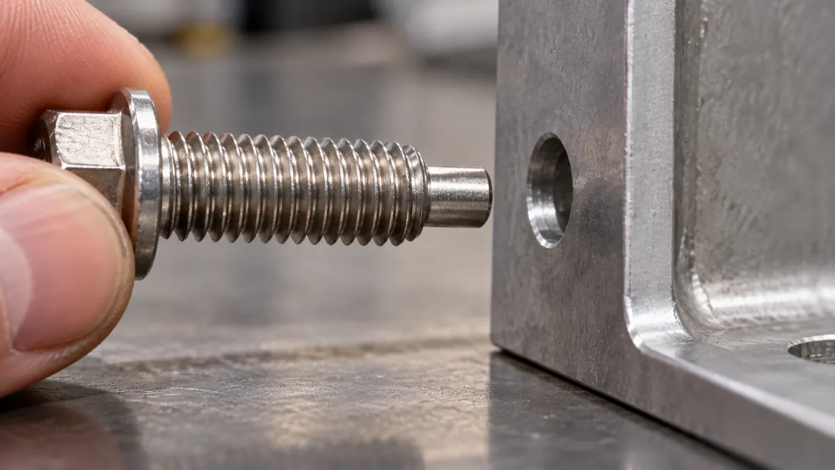
During assembly, a screw may need to pass through a clearance hole and engage a nut, threaded plate, or other mating feature. If access is limited or the holes are not perfectly coaxial, a shaped extended tip can help locate the receiving feature before the thread begins to carry the engagement. This can make initial alignment easier in some assemblies, but the allowed offset and angle depend on the point form and joint geometry.
Bulten’s product reference distinguishes dog point from pilot point terminology and notes that extended ends can support location and alignment. It identifies a dog point as a reduced-diameter end in relation to the nominal screw length convention, while pilot-point naming and geometry depend on how the extension is specified. Buyers should use the supplier’s controlled drawing and the applicable standard rather than relying on informal names alone. That distinction is essential to a bolt captive screw dog point pilot assembly alignment review.
In a knock-down rack connector, the receiving feature might be a threaded plate or a separate mating component. The alignment challenge may arise from the assembly sequence, limited hand access, or relative movement between parts. A longer pilot may provide more lead-in, but it also needs space beyond the threaded region. If the connector has a blind cavity, a finished surface behind the joint, or limited depth, the extended tip can bottom out or interfere before the head seats.
What should the buyer define before choosing the tip?
Start with the actual assembly stack: the screw, clearance hole, mating thread, plate thickness, washers or spacers, and any surrounding components. Identify which parts are fixed and which can move during assembly. Define the intended direction of insertion and whether a user or installer can see the hole. The objective is not to specify a special point because assembly feels difficult; it is to connect the point geometry to a documented alignment problem.
Then identify the nominal screw and point geometry in the controlled specification. State the screw size and thread, head and drive, under-head length reference, threaded length, and the specific pilot/dog-point configuration required or proposed. Clarify whether the extension is included in the nominal length as defined by the supplier’s standard and drawing. Avoid accepting a supplier’s shorthand “self-aligning screw” without a dimensioned part reference.
The receiving feature also needs to be clear. Specify its hole or thread location, entry condition, depth, and any chamfer or lead-in required by the design. If positional tolerance or assembly float is part of the design, the engineering owner should define it; the supplier should not infer an allowable offset from the presence of a dog point. A point can guide the start but cannot compensate for unlimited positional error.
| Design option | Intended role | Verificação do comprador | Limitação importante |
|---|---|---|---|
| Standard screw end | Thread starts directly at the end geometry | Is the mating hole reliably accessible and aligned? | May provide less guidance before thread contact |
| Dog point | Reduced-diameter cylindrical end can help locate a mating feature | Point diameter/length, entry clearance, thread start and overall length convention | Must not bottom out or reduce required thread engagement |
| Pilot point with lead-in form | Tapered or otherwise shaped lead-in may guide entry, depending on design | Supplier drawing, receiving-hole geometry, allowed offset and tip clearance | Point style does not define a universal alignment range |
| Floating mating component | Allows some relative position adjustment when designed for it | Float range, retention, assembly sequence, and final location | Float is not a replacement for correct datums or control of the final joint |
This comparison is a decision map rather than a product selection chart. The right choice depends on actual geometry, assembly sequence, and evidence—not merely the name of the screw point.
How does pilot alignment differ from thread engagement?
Thread engagement concerns how much of the screw’s thread participates in the mating thread, along with bottom clearance and other joint details. A dog point or pilot tip concerns how the screw approaches and enters the mating feature before or as the threads begin to engage. A screw can have sufficient thread engagement and still be difficult to start if the parts are misaligned; conversely, an easy-to-start pilot does not prove adequate engaged thread length.
Keep these checks separate in a supplier review. Do not add pilot length by shortening the threaded region without checking the required engagement. Do not assume the point’s reach is available inside a blind hole. Confirm the screw’s overall length convention and the geometry from the head bearing plane to the point, especially if the purchase description is ambiguous.
Likewise, distinguish a self-aligning point from a thread-forming or anti-cross-thread feature. Some proprietary systems combine a pilot with special thread transitions; those designs have their own controlled geometry and cannot be reduced to “a longer dog point.” If the supplier proposes a branded or specialized fastener, evaluate it as a specified system and confirm the compatible mating feature.
What should the sample assembly demonstrate?
Use the approved connector plates, screw, mating thread, and any spacers in the same relative arrangement expected in the product. Identify all part revisions and the proposed fastener source. Demonstrate initial approach, pilot entry, thread start, final seating, and clearance beyond the tip. Observe whether the screw starts without forcing parts together or damaging the thread. The sample should represent the designed assembly condition, not an artificially aligned bench setup if the real product has a different sequence.
If the buyer expects the tip to accommodate a defined positional offset, the engineering owner should state the test condition and acceptance criteria. Do not treat the fact that one assembly could be hand-started as proof of a universal offset tolerance. Where the assembly has limited visibility, assess it from the user’s actual access direction. If the pilot can contact a finished surface, confirm the clearance at final seating and through the assembly motion.

Record the sample identity, drawing revision, fastener part number, point dimensions or drawing reference, mating-hole condition, and review result. If the result is borderline or inconsistent, document the assembly condition and ask the responsible design or supplier engineer to investigate. Do not replace a geometric specification with a verbal statement that the screw “self-aligns.”
Which failure modes remain possible?
Cross-threading may still occur if the screw approaches at an unsuitable angle, the mating thread is damaged, or the parts are beyond the intended alignment range. A pilot can help guide entry but does not establish that threads are correctly engaged. The sample review should observe both the lead-in and subsequent thread start.
The pilot can also bottom out. In a blind receiving feature, the remaining depth after engagement matters. Check the complete stack at final seating, including any washer or plate. A tip that reaches the bottom too early can prevent the head from seating or alter the intended clamp condition. The permitted condition depends on the design; no generic clearance value should be invented.
An extended point can interfere with nearby hardware or a finished face. The design should include enough space for insertion and final assembly without allowing the tip to scratch, snag, or contact an unintended component. If the fastener is used in a multi-part connector, review the entire path rather than only the receiving hole.
Finally, a point-style substitution can change length, thread runout, head-to-thread geometry, or supplier identification. Require the revised drawing and sample before approving a different profile. If the fastener source changes, verify that the approved characteristics remain controlled and that the purchase documents map to the correct item.
How should the buyer balance ease of assembly and specification control?
Ease of assembly is valuable, particularly for flat-pack or knock-down products, but it should not be pursued by hiding an unresolved tolerance problem. First determine whether the alignment issue is caused by the connector design, assembly sequence, hole location, fixture, or fastener lead-in. Then compare the lowest-complexity viable change. The answer may be a pilot feature, a better lead-in, a different sequence, or a design adjustment; it is not automatically a more specialized screw.
Consider sourcing consequences as well. A nonstandard point can affect part availability, minimum order quantities, cost, and replacement compatibility. Ask the supplier to identify standard versus custom geometry and to quote alternatives against the same drawing and sample criteria. Do not assume cost savings or reduced assembly time without a comparable production quote or measured project evidence.
For a small-batch OEM project, a dimensioned drawing and an approved physical sample can provide a practical basis for discussion. Record who owns the design change, how a fastener substitution is approved, and which revisions require another sample. The buyer retains control of the product specification while allowing the supplier to recommend a manufacturable solution.
What belongs in the RFQ and approval record?
State the rack connector and screw revisions, mating thread/hole geometry, assembly direction, required access, and the alignment problem being addressed. Identify whether a dog point or another pilot geometry is mandatory or merely a supplier proposal. Ask for the controlled fastener drawing, dimensional references, and confirmation of how point length is included in the overall dimension. Define any test offset or acceptance condition only when the design owner has established it. These details make bolt captive screw dog point pilot assembly alignment reproducible across RFQs and repeat orders.
During approval, retain the sample IDs, supplier part number, configuration, assembly observation, tip-clearance review, and any unresolved risks. Specify that changes to point geometry, screw length, thread, mating feature, source, or assembly sequence require review if they can affect alignment or seating. This gives purchasing a clear basis for repeat orders without implying that a point feature alone prevents all assembly errors.
Perguntas frequentes
Is a dog point the same as a pilot point?
Terminology and dimensional conventions can differ. Bulten describes dog-point and pilot-point forms separately and references ISO 4753. Use the controlled supplier drawing and applicable standard to identify the exact feature being purchased.
Does a pilot tip eliminate cross-threading?
No universal guarantee follows from the tip shape. It may help the screw locate the mating feature, but alignment, thread condition, access, and the receiving geometry still matter. Verify the actual sample and do not assume every failure mode is removed.
Can the point compensate for a misplaced hole?
Only within a design-validated range, if any. The allowed positional relationship must come from engineering requirements and representative testing; do not infer it from the presence of an extended tip.
Can a longer pilot reduce thread engagement?
It can change the portion of the fastener available for thread engagement, depending on the length convention and geometry. Confirm both the pilot dimensions and required engaged thread on the controlled drawing.
What should be checked in a blind connector?
Verify the pilot and threaded portion do not bottom before the head reaches the intended seated position, and confirm the thread engagement required by the design. Use the actual stack and specified acceptance method.
Does this article establish Koitor’s fastener range?
No. It is a buyer evaluation framework. A particular screw type, source, or assembly capability must be confirmed for the project.
Source
Review a Rack-Connector Fastener
Share the rack-connector drawing, mating feature, and sample assembly question you need a supplier to review. Koitor can discuss manufacturing and sourcing requirements within the confirmed project scope; the final fastener specification and acceptance criteria must be approved for the product.
OEM / MARCA PRÓPRIA
Transforme este guia de fornecimento num resumo do produto
Indique o produto pretendido, as dimensões, o acabamento, a quantidade a encomendar e os requisitos de embalagem. A sua equipa receberá uma análise prática da viabilidade de fabrico antes da apresentação do orçamento.

 English
 Español
 Português
 Français
 Deutsch
 العربية