
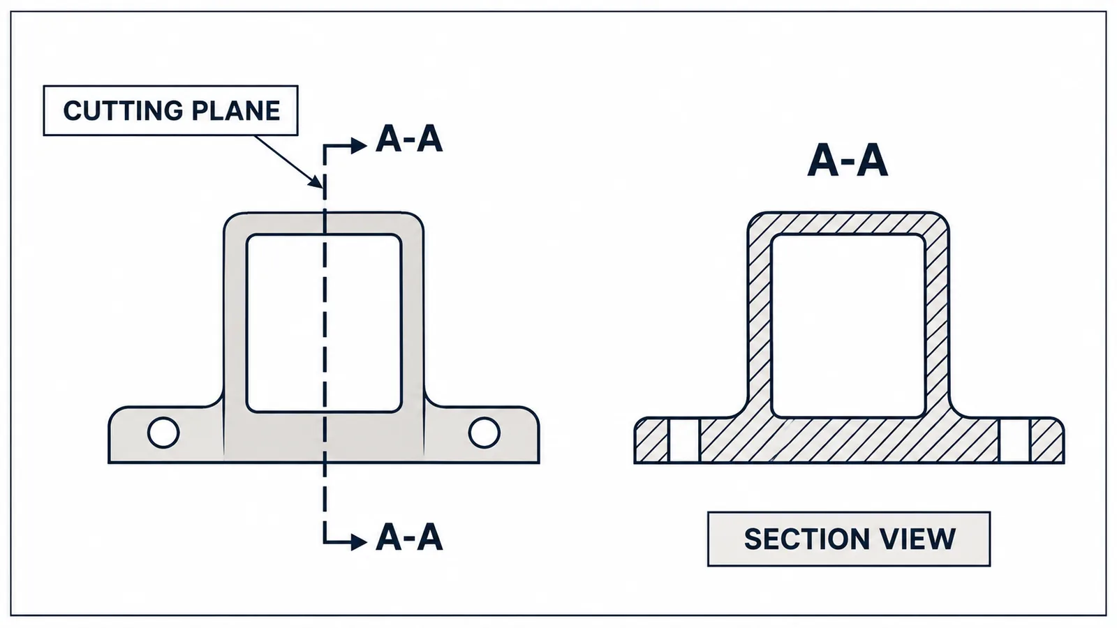
A section view drawing shows internal geometry as if a part or assembly were cut along a defined plane. To read one, first match the section label to its cutting-plane reference, then follow the arrows and compare the section with the related exterior view. Hatch marks commonly identify material intersected by the cut, while an unhatched area may represent a hole, cavity, gap, or component treated differently by the drawing convention. A section view helps a buyer ask clearer questions about hidden features, but it does not replace controlled dimensions, material specifications, revision status, or supplier confirmation.
What problem does a section view solve for a buyer?
An exterior view can show the width and height of a metal part while concealing the feature that determines whether it can be assembled. A hollow tube may look solid from the side. A mounting plate may hide a counterbore. A bent bracket may have a return flange whose depth is difficult to infer from a front elevation. A section view makes a selected interior slice visible so that the reader can understand the relationship between an outer boundary and features inside it.
For a buyer, the value is practical: it can reveal whether a quotation, sample, or proposed revision appears to include the feature that the product requires. A section can clarify a tube wall, a recess, a pocket, a passage, or the position of one component relative to another. It can also expose ambiguity. If the cutting plane misses the feature under discussion, the section cannot answer the question, even if the drawing contains several other views.
The drawing remains a communication document with a defined scope. A section illustrates geometry according to its references and conventions. It is not a physical test, a material certificate, or proof that the manufactured part matches the drawing. Buyers should use it alongside the revision-controlled drawing, bill of materials where applicable, approved sample, and inspection criteria. When a feature is functionally important, make the requirement explicit instead of relying on a reader to infer it from a small illustration.
How to locate the matching section view
Begin with the view label, often a letter or paired identifier such as A–A. Find the corresponding cutting-plane reference on the related view. The line may be straight or may change direction for an offset section; arrows indicate the viewing direction. The same identifying label should connect the section view to the plane that produced it. If labels are missing, duplicated, clipped, or inconsistent between sheets, pause before using the section to approve a feature.
Do not assume that a section is always placed directly beside the view that contains its cutting plane. Page layout, projection arrangement, detail callouts, and software settings can vary. Read the title, view labels, leaders, and drawing notes together. If the drawing uses multiple sections, trace each reference independently. A-A on one sheet and A-A on another sheet may not be related unless the drawing set establishes that relationship.
Arrows matter because they show the direction from which the cut face is viewed. A buyer who follows only the cutting line can reverse the apparent orientation of a feature. For example, a notch shown on the left side of a section may belong to a face that appears at the right in another view, depending on the viewing direction and projection arrangement. Use a known outer edge, hole, bend, or assembly feature to orient the views before comparing them.
When the drawing cannot be reconciled, ask for a marked-up clarification that names the sheet, view label, feature, and revision. A useful clarification request might say: “Please confirm whether section B–B passes through the mounting boss shown in detail C, and identify the controlling dimension.” This is clearer than asking a supplier to “check the inside.” The buyer should preserve the answer with the drawing revision so that later quotation and sampling discussions refer to the same geometry.
What does the hatch indicate?
Hatching is a visual convention used to show material intersected by a section plane. A solid region crossed by hatch marks can indicate the cut material, while an open region may show a void such as a hole or cavity. The pattern is a graphic aid. It does not identify the alloy, grade, coating, hardness, wall thickness, or structural performance. A hatch pattern can also be affected by component boundaries, assembly conventions, drawing scale, and the way a CAD system displays the view.
In an assembly section, adjacent parts may use different hatch directions or spacing to help distinguish them. Some components may be represented according to specialized drafting conventions. Fasteners, thin features, ribs, and other items can be treated differently depending on the governing drawing practice and context. Therefore, do not apply a blanket rule such as “every cut component must be hatched” or “all fasteners are excluded.” Read the notes and project standards that actually apply, and ask the document owner when the depiction is ambiguous.
A blank area should not automatically be called an empty cavity. It may be a hole, a passage, a separate component, or a portion not intersected by the cutting plane. Compare the boundary with other views and look for centerlines, hidden edges, leaders, detail views, and dimensions. If the purpose is to show a continuous bore or drainage path, request a view or note that makes that requirement explicit. A buyer should not treat an illustration as a substitute for a clear acceptance criterion.
| Drawing cue | What it can help show | O que isso, por si só, não demonstra |
|---|---|---|
| Section label | Which cut view is being referenced | That two sheets share the same reference without a defined link |
| Cutting-plane line | Where the object is conceptually cut | A manufacturing tolerance or inspection method |
| Arrow direction | The viewing direction for the section | The physical installation orientation unless other views define it |
| Hatch marks | Material represented at the cut | Material grade, wall thickness, or test performance |
| Unhatched region | A possible opening, cavity, or uncut feature | That a passage is continuous or functionally adequate |
Full, half, and offset sections answer different questions
A full section uses a cutting plane through the object to expose an interior profile. It can be useful when the relevant features lie along one path, such as a passage through a formed or machined component. The section may simplify interpretation by showing internal boundaries that would otherwise require hidden lines. It does not reveal every feature in three dimensions: it shows only what is represented by the selected cut and view.
A half section can show an exterior half and a sectional half in one view for an object with a suitable symmetry or clear center reference. This can help a reader compare inside and outside relationships without switching between separate views. The reader should still identify the division line and confirm whether the object is actually symmetric in the relevant region. A familiar-looking half section does not prove symmetry beyond the depiction.
An offset section uses a cutting plane that bends or shifts to pass through several features that do not lie on one straight line. The resulting section is presented as a single view according to the drawing convention. The offset route is a communication device; it should not be interpreted as a literal bent internal surface. If a buyer needs the distance or relationship between features, the drawing should dimension those features rather than relying on visual measurement from the offset depiction.
A removed section, revolved section, local section, or detail view may serve a narrower purpose. These forms can make a small feature easier to understand, but the title and leader determine their scope. A local breakout, for instance, may expose only a selected area. Do not assume that unshown areas share the same internal construction. If a quotation depends on an internal feature that is not covered, request the missing detail before comparing price or approving a sample.
Section view versus hidden lines, detail views, and exploded views
A section view is not an exploded view. A section exposes an interior by representing a cut through material. An exploded view separates components visually to explain assembly relationships. A part may therefore appear intact in an exploded view but be cut in a sectional view. Using the wrong view type can lead a buyer to confuse a physical gap with an illustration used only to show assembly.
Hidden lines show edges that are not directly visible in a particular projection. They can help document concealed geometry, but a dense set of hidden lines may be difficult to read where features overlap. A section can make some of those relationships clearer by replacing selected hidden edges with a cut representation. The choice of view depends on the question and the drawing conventions, not on a universal preference for one style.
A detail view enlarges a selected area. It may show a small hole, edge, bend, or interface more clearly, but it does not necessarily expose the interior. A section detail combines enlargement with a cut. Check the detail boundary and label to understand exactly what was enlarged or sectioned. If a critical feature is only implied in a low-resolution screenshot, ask for the original controlled drawing or a clear extract.
An isometric view is useful for spatial orientation but often does not control dimensions. A perspective image can make a part easier to visualize; it should not be used to estimate an internal radius, wall thickness, or hole depth unless the drawing explicitly defines those values. Keep separate the purpose of a view—orientation, dimensioning, assembly explanation, or interior display—when reviewing a supplier file package.
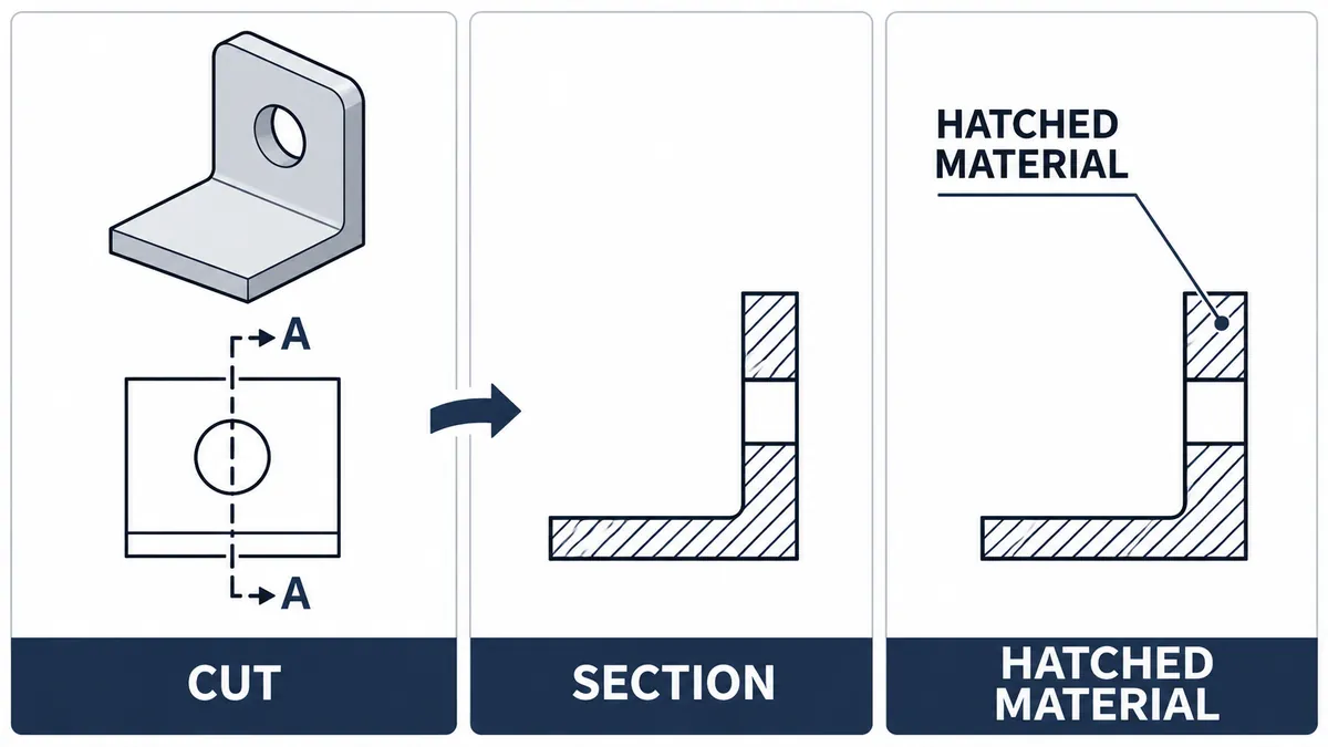
Reading a section view drawing before quotation or sample approval
Use a repeatable sequence rather than trying to decode the entire sheet at once. First confirm the drawing number, revision, units, projection symbol if present, and notes that govern interpretation. Then identify the relevant part or assembly and locate the view labels. Find the cutting-plane reference and trace the arrows to its matching section. Only after these steps should you interpret hatch, holes, walls, and interfaces.
Next, identify the buyer decision connected to the feature. Is the question whether a tube is open or capped? Whether a mounting plate has a recess? Whether a fastener passes through a component? Whether two parts touch or have a clearance? A section view may help answer those questions, but the requirement should be written in a measurable or observable form. For example, “show the through-hole and identify its controlling diameter” is more actionable than “make this area like the picture.”
Compare related views. A section is easier to orient when matched against an exterior elevation, plan view, detail, or assembly view. Use a consistent landmark such as a hole center, flange, weld symbol, or bend. If the views seem inconsistent, do not choose the one that appears more convenient. Ask which view controls, whether a revision superseded another, and whether a change was intentionally made.
Record unresolved points before a supplier quotes. Make a short issue list with the drawing page, section label, feature, question, and requested evidence. Evidence might be a corrected section, a dimension, an annotated sample photo, or a first-article measurement, depending on the project. Do not demand a specific test or certificate unless the project actually requires it and the supplier’s role is clear.
What section views mean for metal hardware sourcing
Bathroom and home-storage hardware can combine wire, tube, sheet, brackets, fasteners, end caps, and finish layers. A section view may communicate a folded edge, hollow tube, insert, internal reinforcement, mounting interface, or drainage path. The view is helpful when it captures the relevant geometry, yet the drawing must still state the material, finish, critical dimensions, revision, and inspection expectations separately.
For a bent sheet-metal bracket, a section may illustrate the relationship between flanges or show how a fold returns behind a visible face. For a tube assembly, a cut may show whether the tube is represented as hollow and how an insert fits. For a wall-mounted accessory, a section may show the offset between a mounting plate and the visible product body. These are generic examples, not claims that any particular Koitor product uses the pictured construction. Confirm the actual project design and component scope.
A section view can reduce misinterpretation during drawing review, but it does not automatically make an RFQ complete. The supplier may also need overall dimensions, tolerances, material and finish requirements, quantity, packaging, logo artwork, target market, and sample expectations. If a feature affects fit or function, label its criticality and acceptance method. If the buyer is still deciding the concept, mark the drawing as preliminary so it is not mistaken for a production release.
When a custom product is under development, drawing changes should be tracked. A new section may alter an internal clearance while leaving the exterior view nearly unchanged. A revised wall, insert, or bend can affect assembly sequence, tooling, finish access, or packaging, depending on the design. Ask the supplier to identify affected features and confirm the revision before approving a sample. Do not infer that a geometry change has no cost or lead-time effect without a project-specific review.
Autodesk’s CAD documentation describes section views as a way to reveal interior features through a cutting plane and explains that full, half, and offset treatments serve different drawing purposes. That documentation is useful for understanding the general concept, but software-specific settings are not a substitute for the conventions stated in a project drawing. A buyer should follow the issued view labels, arrows, notes, and dimensions, then ask the drawing owner to resolve any conflict. See the AutoCAD section-view documentation e o Inventor section-view documentation for software-context explanations.
Common section-reading mistakes
Reading hatch as a material specification. Hatch marks show a cut representation, not a grade or finish. Put material and finish in the appropriate specification field or note.
Confusing a blank area with a confirmed hole. The open area may be a void, an uncut region, or a separate component. Compare views and request a defined feature when it matters.
Ignoring the arrows. The viewing direction can reverse apparent left-right relationships. Orient the section using recognizable landmarks.
Assuming the section covers the whole part. A local or offset cut may serve a limited explanatory purpose. Confirm the section extent and use other views for features outside it.
Measuring from a screenshot. Scaling a raster image is unreliable unless the drawing provides a valid scale and the image has not been resized. Use stated dimensions and ask for clarification where needed.
Mixing revisions. A section view from an old file can conflict with a new exterior view. Confirm drawing identity and revision across all pages and attachments.
Using an illustration as an acceptance standard. If a hidden feature matters, state how it will be checked. A section in a design drawing is not proof of the finished part’s internal condition.
Assuming software defaults are universal. CAD applications offer settings for section lines, hatching, view placement, and component participation. Defaults vary. The issued drawing and applicable drafting convention control.
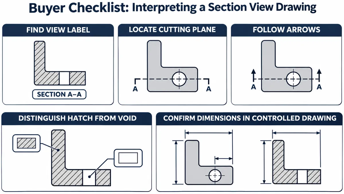
Buyer checklist before requesting a quotation
- Confirm the drawing number, revision, units, and status.
- Match each section label to the correct cutting-plane reference.
- Follow arrows to establish viewing direction.
- Compare the section with related exterior and detail views.
- Identify which areas are cut, open, separate, or uncertain.
- Confirm critical dimensions from the controlled drawing, not a screenshot.
- State the material, finish, component, and assembly requirements separately.
- Identify the feature that affects fit, function, appearance, or packaging.
- Mark any unresolved question with a sheet, view, and feature reference.
- Ask what evidence will confirm the feature on a sample or production part.
- Include the approved revision with the RFQ and sample feedback.
Perguntas frequentes
What is a section view drawing?
It is a technical view that represents an object as if cut along a defined plane so selected internal geometry can be shown. Read it with its label, cutting-plane reference, arrows, other views, dimensions, and notes.
Do hatch marks identify the material grade?
No. Hatching usually identifies material represented at the cut. It does not establish alloy, coating, thickness, certification, or mechanical properties. Those requirements need separate specifications and evidence.
Does every section show the entire inside of a part?
No. A full, half, offset, local, or removed section can expose different portions. Confirm the cut extent and whether the feature under discussion lies on that plane.
Can I approve a part from a section view alone?
Usually not when approval depends on dimensions, material, finish, fit, or performance. Use the complete controlled drawing and the project’s sample or inspection criteria. Ask for clarification when the representation is ambiguous.
How is a section different from an exploded view?
A section represents a cut through an object to show interior geometry. An exploded view separates components to explain their arrangement. They answer different questions.
What should I do when a section and another view appear inconsistent?
Record the drawing revision, sheet, view labels, and feature, then ask the document owner which representation controls. Do not resolve a conflict by measuring a low-resolution image or choosing the preferred view without confirmation.
Does a section view define how the part will be manufactured?
Not by itself. It communicates geometry, but process selection, tooling, tolerances, material, finish, and inspection require their own project-specific information and supplier review.
What evidence should close an open drawing question?
Choose evidence that answers the unresolved question directly. If the uncertainty is about where the cut passes, request an annotated drawing with the cutting-plane path and view label. If it concerns a dimension, request the controlling value and tolerance on the controlled drawing. If it concerns the physical sample, identify the feature and agree how it will be observed or measured. A photograph may help orient the discussion, but it can hide depth, scale, or the far side of a part. Keep the response with the revision that it clarifies, and ask the supplier to flag any related change to material, finish, assembly, or packaging. This creates a useful record for quotation and sample review without suggesting that a single section view can certify the finished product.
Need a Drawing or Sample Reviewed for an OEM Hardware Project?
Share the controlled drawing or physical sample, revision, intended use, and the exact feature that needs clarification. Koitor can review the scope for relevant bathroom and home-storage hardware projects; feasibility and responsibilities depend on the supplied specifications.
OEM / MARCA PRÓPRIA
Transforme este guia de fornecimento num resumo do produto
Indique o produto pretendido, as dimensões, o acabamento, a quantidade a encomendar e os requisitos de embalagem. A sua equipa receberá uma análise prática da viabilidade de fabrico antes da apresentação do orçamento.



 English
 Español
 Português
 Français
 Deutsch
 العربية