
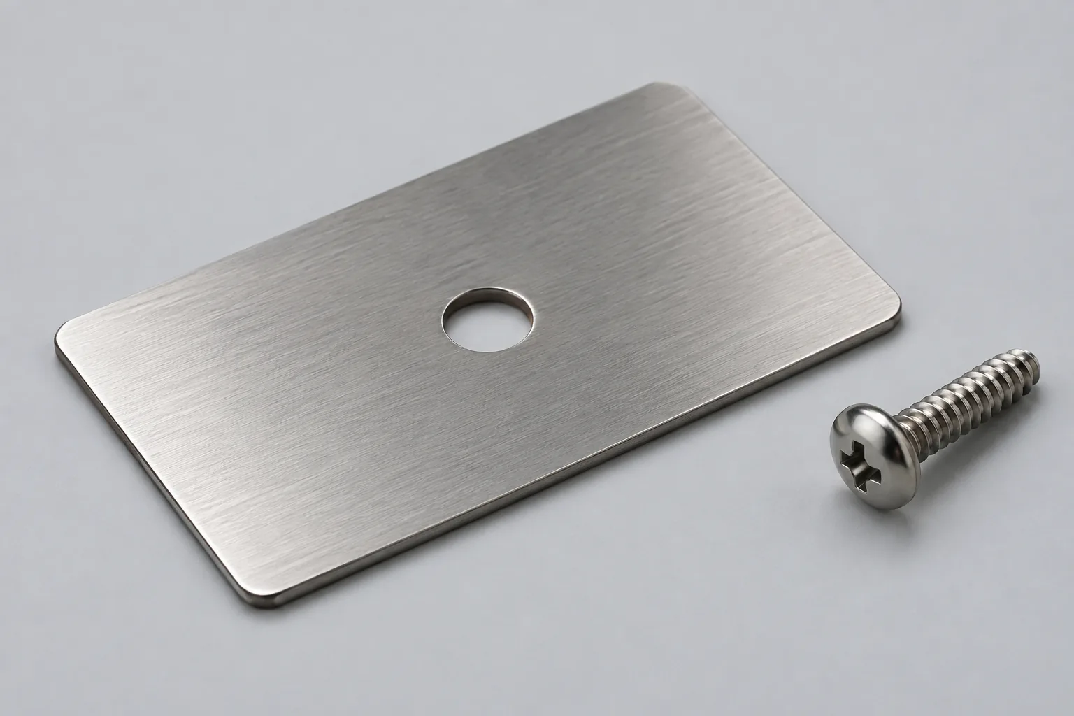
Punching burr direction matters when a mounting plate��s edge touches a mating surface, slides into an assembly, or remains accessible to a user or installer. Buyers should identify the functional face and the side from which the punched feature is formed, then define how the finished edge will be handled and checked. A drawing that shows only a hole diameter may leave the supplier unsure which side may contain the exit-side edge or whether deburring is required.
Why Do Punched Holes Have Different Edge Zones?
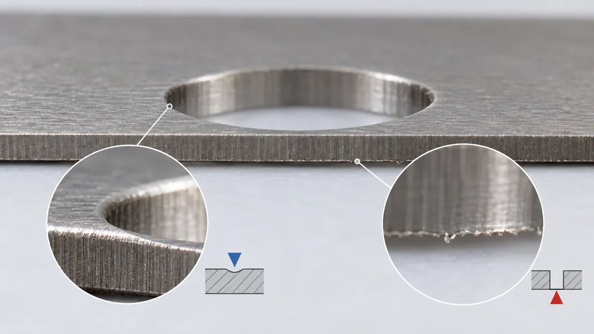
Punching is a shearing operation: the punch and die act on sheet metal, and the material passes through deformation, cutting, and separation. A punching-process overview from TRUMPF describes those stages and explains how the punch and die cut the sheet. Tool condition, material, thickness, clearance, and the part��s geometry influence the resulting edge. The appearance can include a rounded entry, a sheared region, a fracture region, and a small exit-side burr. The exact edge profile depends on the process and part; buyers should confirm it on the actual component rather than treating a diagram as a guaranteed result.
The two faces of a punched plate may not be equivalent. A mounting face that sits against a wall, bracket, or adjoining panel can be more sensitive to an edge that raises the plate or scratches its mate. A free edge that is covered after assembly presents a different concern from a hand-accessible perimeter. Hole location and diameter may pass dimensional inspection while the edge orientation still affects fit, seating, coating coverage, or handling.
This is why punching burr direction should be a drawing or sample-review decision, not an assumption. State the preferred orientation relative to the product��s visible and functional faces. If the exact orientation is not critical, say so; if a particular face must be smooth or deburred, identify it and define the acceptance method. Avoid using ��no burr�� as a vague requirement without agreeing what it means for the material, feature, process, and application.
Which Side Should Face the Mating Part?
Start with function. Identify the face that contacts the mounting surface, the direction in which fasteners are installed, and whether a punched edge is exposed, covered, or close to a hand or cable. Then consider the assembly sequence: a part may be turned over during production, finishing, packaging, or installation. A simple orientation mark or drawing view can prevent a supplier from interpreting ��front�� differently from the buyer.
Do not automatically prescribe that the burr always face away from the mating surface. That may be a useful starting discussion, but the correct orientation depends on the joint and design. A raised edge could interfere with flush seating or create a gap; a sharp exposed edge may present a handling concern; a deburring operation could affect dimensions or finish. Some parts may need controlled deburring on both sides, while another feature may be acceptable as punched if it is hidden and does not interfere.
The buyer should also distinguish hole-edge condition from plate flatness and hole position. If a plate rocks on a reference surface, the cause could be an edge, distortion, a formed feature, or another geometry issue. If the fastener does not align, hole location, datum selection, stack-up, or assembly access may matter. Record the observation first, then establish the cause with measurement or a controlled sample comparison.
What Should the Drawing and RFQ Specify?
For each critical punched hole or slot, identify the size, location datums, part orientation, material and thickness requirement where known, and which face is functional or visible. Show the mating component or assembly direction if it affects edge acceptance. A 2D drawing may need a section or detail view when the required face or edge treatment is otherwise ambiguous.
Use separate notes for separate decisions. For example, one note can define the mounting face; another can define whether that face��s hole edge must be deburred; a dimensional callout can control the hole itself. If a coating or plating process follows punching, specify whether the edge condition is reviewed before or after finishing. Do not assume coating will remove a burr or make an unacceptable edge harmless.
If a buyer expects a particular deburring outcome, explain the functional reason: flush contact, assembly clearance, appearance, handling, or another project requirement. Then agree how it will be evaluated. A visual inspection, tactile check, dimensional measurement, or fit test answers different questions. Any sharp-edge limit or tactile standard should come from the project��s product and market requirements, not an invented universal value.
For tool and process discussions, provide the material, thickness, feature dimensions, drawing revision, target quantity, and any mating-part information. The tooling supplier��s ordering guidance similarly requests application-specific information such as machine and tool type, dimensions or drawings, sheet thickness, material, and quantity. That is useful context for an RFQ; it does not establish that a particular tool, machine, or process is available at Koitor. Koitor��s approved capabilities include punching and metal fabrication, but the exact part route and tooling needs must be confirmed project by project.
How Can Buyers Compare Edge-Control Options?
Not every mounting plate needs the same treatment. The table below separates orientation from edge finishing and dimensional control. The options should be selected against the mating condition and sample evidence, not applied automatically to every punched feature.
| Option | When it may help | Trade-off to review | Evidence to agree |
|---|---|---|---|
| Specify punch direction only | When the functional face must be protected from the exit-side edge | Does not define burr size, edge feel, or hole tolerance by itself | Drawing view, part orientation, and production-intent sample |
| Deburr one identified face | When one side contacts a mating surface or remains exposed | May affect edge profile, coating, dimensions, or processing time | Named face, method or outcome, and post-process check |
| Deburr both faces | When both sides matter for fit, handling, or assembly sequence | Additional operation may alter the edge or add process steps | Sample comparison and a defined acceptance method |
| Use a fit or seating check | When the key requirement is flush contact or assembly fit | Fit alone may not characterize every exposed edge | Mating component, support condition, and pass/fail criterion |
| Use a dimensional edge check | When a defined hole or feature measurement is critical | Measurement does not automatically establish safe handling or visual quality | Datum, instrument, measurement zone, and agreed limit |
A secondary deburring operation can be considered when the punched result does not meet the agreed functional or edge requirement. It should not be added blindly: the supplier and buyer should check whether it could change the feature size, plate flatness, surface finish, or fit. If the requirement can be met by orienting the part correctly, extra processing may be unnecessary. If a consistent edge is critical, the sample should demonstrate the proposed operation and its effect on the finished assembly.
How Should Buyers Qualify a Production-Intent Sample?
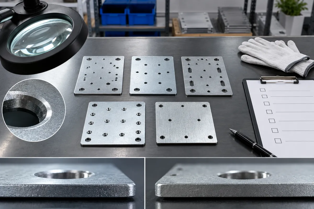
Use a sample made with the intended material and thickness, punched feature, orientation, and relevant finishing route. Record any difference from the planned production process. A hand-finished prototype may answer whether a layout fits, but it may not establish the edge condition produced by the intended tool and operation.
Review the part against the drawing. Confirm the mounting face, hole locations and sizes using the specified datums, and inspect the designated edge treatment. If there is a mating bracket or wall plate, check the assembled fit under a defined condition. Avoid holding or clamping the sample in a way that hides a seating issue. If the part is installed with fasteners, use the intended assembly direction and adjacent components where available.
Record observations in objective language. ��Raised edge visible on the reverse side of hole A after punching�� is more useful than ��bad burr.�� Note the sample ID, revision, material/finish information, inspection method, result, and disposition. If the sample fails, decide whether the likely next step is orientation change, deburring, tooling review, design adjustment, or additional evidence. Do not claim a root cause until it has been checked.
Where several holes serve different functions, do not assume one edge note covers every feature. A locating hole, clearance hole, screw seat, and open slot may have different contacts and assembly directions. Identify the critical ones on the drawing or in an inspection plan. If a part is symmetrical and can be flipped, specify how the supplier can recognize the intended face, such as a drawing view, temporary sample mark, or assembly reference that does not remain on the finished product unless approved.
When comparing supplier proposals, ask what is included in the quoted edge treatment and at what stage it occurs. ��Deburred�� can refer to different manual or mechanical approaches and does not automatically mean the hole size, finish, or fit is unchanged. Compare the actual sample and stated process; if the method is undecided, record it as an open development point instead of assuming identical outcomes from similar wording.
Where tool wear may affect repeat production, ask the supplier how the relevant edge and hole features are monitored and what triggers review. The control plan should match the part��s risk and order context. A sample approval establishes agreement on the identified sample and criteria; it does not by itself guarantee every future batch or establish an unsupported performance claim.
For repeat orders, connect the approved sample to a controlled drawing revision and a practical inspection record. Buyers can agree which features receive routine checks, what evidence is retained, and how a reported deviation is handled. The frequency and method should reflect the order, product risk, and supplier process rather than a copied universal sampling rule. If a tool is reground, replaced, or set up differently, ask whether the change can affect the hole edge or its orientation and whether a first-piece review is appropriate. A clear change-notification path helps keep the approved sample meaningful without promising that every process variable will remain identical forever.
What Should the Buyer��s Punching Checklist Include?
Before releasing the drawing or approving a sample, confirm the punching burr direction and edge-treatment expectations:
- Identify the mounting plate��s function and the mating surface or component.
- Mark the visible face, functional face, and assembly direction on the drawing.
- Specify material, thickness, hole or slot dimensions, datums, and part revision.
- State whether the edge should remain as-punched, be deburred on one face, or be treated on both faces.
- Define the inspection stage: after punching, after deburring, after finishing, or in the assembled condition.
- Agree the check method for fit, flush seating, exposed-edge condition, and critical dimensions.
- Provide the mating part or a representative assembly reference where it changes acceptance.
- Record sample differences, inspection results, deviations, and written approval.
- Ask what tooling or process changes could affect the edge and whether requalification is needed.
- Keep any sharp-edge, safety, or compliance requirements tied to the market and project specification.
What Do Buyers Commonly Ask About Punching Burrs?
Does every punched hole have a burr?
The resulting edge depends on the material, thickness, tooling, process, and subsequent operations. Buyers should inspect the actual feature and define acceptance instead of assuming a perfect edge or a fixed burr condition.
Should a burr always face away from the mounting surface?
Not as a universal rule. The functional face, joint design, finish, and assembly direction determine which orientation is acceptable. Confirm the decision on a representative sample.
Does deburring improve every mounting plate?
It may help when an edge affects fit, handling, appearance, or assembly, but an extra operation can also affect dimensions, finish, and cost. Verify the result against the project requirement.
Can a hole pass its diameter check but still cause a problem?
Yes. A diameter check does not by itself evaluate hole position, edge condition, seating, or tool access. Use checks that match each functional requirement.
Can buyers specify a universal burr-height limit?
A limit should be defined for the product, material, feature, and applicable market requirements. Do not copy a value from another part or application without confirming the method and relevance.
Review a Punched Mounting Plate for Your Product
Send Koitor your drawing or physical sample, material and finish requirements, mating-part context, target quantity, and the edge condition that matters. Our team can review manufacturability and sample-development options; the specific punching route and acceptance criteria are confirmed for each project.
OEM / PRIVATE LABEL
Turn this sourcing guide into a product brief
Share your target product, size, finish, order quantity and packaging requirements. Your team receives a practical manufacturability review before quotation.
 English
  Español
  Português
  Français
  Deutsch
  العربية